
Installation manual


M1EZ8 Installation and Programming
Page 10
AC Failure, Low Battery, and Automatic Low Voltage Shutdown
During an AC power failure the battery automatically takes over and AC Fail trouble annunciates at the keypad. The
communicator can be programmed to report AC Fail to the Central Station after a time delay (see Menu 12, System Option 01).
If the battery voltage falls below 11.2 VDC a Low Battery Trouble condition will occur. The communicator can be programmed
to report Low Battery to the Central Station. The battery will continue to run the control until its voltage drops below 10.2 VDC,
at which time the control will disconnect and shut down to prevent a false alarm and damage to the battery. The AC Fail
trouble display will clear if the AC restores. However, the Low Battery Trouble requires a manual or automatic battery load test
before it will clear. An automatic battery load test is performed every 24 hours. See Section 2.2 for powering up the control.
Telephone Line Connection (R1,T1,T,R)
The telephone interface is connected by the use of an approved RJ-31X interconnect jack. This device allows the subscriber
to disconnect the control/communicator from the public switched telephone network in the event of a malfunction. The control
is equipped with line seizure so that the premises telephone service is interrupted during communication to the central
station. Connection to the approved jack is done with a RJSET cord which connects the control terminals to the RJ31X jack.
NOTE: The Telco cord can be supervised to the RJ31X or demarc block by installing an EOL resistor across the Orange and
Blue wires (RJ31X terminals 2 and 7). In the control, connect the Orange and Blue leads to any 24hr Burglar zone input.
Outputs
There are 12 outputs on the main board. In programming these are numbered Out2, Out3, and Out 7 thru 16. The total
outputs may be expanded utilizing output expander boards connected to the RS-485 4-wire Keypad data bus. The Alarm
Output (Out 2) trips when any alarm is activated. All others must be enabled through the RP Rules Programming and can be
triggered by multiple conditions “events”. Do not exceed the current limits on voltage only outputs.
Output 2 - Connect a UL Listed Bell or Siren (self-contained). Current limited to 1 Amp. Program Global Option 26 to Voltage.
This output is supervised. Speaker(s) are only permitted for non-UL installations. Series/parallel wire to avoid dropping
below a 4 ohm total load.
Output 3 is a Single Pole Double Throw Relay with form “C” contacts (Com, N/O, and N/C).
Outputs 7, 8, 9, 10, 11, 12, 13, 14, 15, and 16 are low current, positive (+) voltage only, for driving LEDs, relays, etc. Outputs 4,
5, and 6 ARE NOT available from the main board. They can only be accessed with a data bus Output expander set to
address 1. This expander will replicate main board outputs 7 thru 16, while also including outputs 4, 5, and 6.
Earth Grounding
Tests have determined that the best results against lightning and transients are obtained by isolating the control from ground.
Do NOT connect any of the terminals, especially the Neg. terminals to earth ground. Early production boards had an earth
ground terminal. This terminal is no longer used on circuit board revision I or later. However, ancilliary devices such as the
ELK-950 Surge Protector on the incoming Telephone circuit are still recommended.
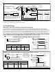
Keypad & Expanders on the RS-485 Data Bus (+VKP, Data A, Data B, Neg)
Keypads and data bus expander devices connect to the four terminals marked +VKP, Data A, Data B, and Neg. The keypad
plug-in wire harness color code is: Red +VKP, Green Data A, White Data B, and Black (-) Neg. The +VKP power terminal is
protected by an auto reset PTC device. In the event of a short circuit or malfunction, power will be removed from all devices
until the problem is resolved.
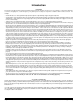
Using Output 7 (low current) with a sensitive relay to switch 24V AC to a Door Strike †
24V AC
Transformer
+
-
Door
Strike †
ELK-924 †
POS
NEG
-T+T
N/OCOMN/C
D3
24V OPEN
N/OCOMN/C
+12V
NEG
16
15
14
13
12
11
10
9
8
7
J16
OUTPUTS
Programmable Outputs (J16) OUT 7 - 16 are +12V switched
positive general purpose outputs rated at 10mA. maximum.
+12V Red
Black
White
Green
Brown
Blue
Yellow
Violet
Pink
Tan
Orange
Grey
+VAUX
NEG
OUT 16
OUT 15
OUT 14
OUT 13
OUT 12
OUT 11
OUT 10
OUT 9
OUT 8
OUT 7
† Not evaluated by UL †† Not for use in UL Listed Systems