
Installation manual


M1EZ8 Installation and Programming
Page 11
Data Bus E.O.L. Termination - VERY IMPORTANT!
The control features a true RS-485 “differential” data bus operating at 38,400 bits per second. This is relatively high speed by
industry standards and ensures fast, accurate communications. With this speed, EOL data bus terminating resistors are
required to eliminate the possibility of reflection errors caused by varying cable lengths. Every data bus device; keypad, zone
expander, etc. and the control board has a built-in bus terminating resistor (120 Ohm) which is installed (activated) via a 2 pin
header/jumper (2 Gold Pins). The hardware pack includes two black shorting caps. When one of the shorting caps is placed
on the two gold pins, it installs (activates) the 120 Ohm terminating resistor across Data Lines A & B. Terminating resistors
are marked JP2 on the keypads and JP1 on the expanders. From the factory, no terminating resistors are installed (activated).
WARNING! The RS-485 Data Bus must NEVER have more than 2 terminating resistors header/jumpers installed.
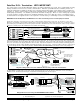
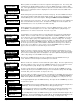
Ideally, there should be no more than 2 home run cables (4 wire) with daisy chained devices along each. The last device on each cable
MUST have a terminating resistor installed (activated) via the gold 2 pin header/jumpers marked JP2 on keypads, JP1 on expanders. Place a
black shorting cap (see hardware pack) onto the 2 gold pins to install a 120 Ohm resistor across data lines A & B. If there is only 1 data bus
cable place a shorting cap on JP3 of Main Board. See alternate hookups below.
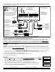
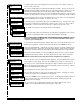
For those that prefer to home run wires, use 6 or 8 conductor (CAT5 is ideal) cable. At each device, make a three way splice of the data A, the
device A wire (terminal), and a return data A1 wire (using one of the extra wires). At the control, make a two way splice of the data A1 return
wire (series connection) to the outgoing data A wire of the next cable. Repeat for the data B wire. Remember to install a terminating jumper on
the last wired device and the control JP3 ONLY! Electrically the data wires are now in series. Connect the POS (+) and Neg (-) power wires of
each device directly to the M1’s +VKP and Neg terminals. DO NOT SERIES THE POWER WIRES as this will cause unnecessary voltage loss.
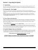
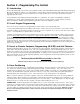
The ELK-M1DBH † Data Bus Hub accepts CAT5 or CAT6 cable with RJ45 plugs on the ends and does all the work of series connecting the
DATA lines A & B. Terminate at the hub using the included RJ45 Terminating Plug in the first unused jack.
+VKP
DATA B
DATA A
NEG
EGND
ELK-M1KP
BLACK
WHITE
GREEN
RS-485 Data Bus (Max. length is 4000 ft.
Max. bus devices vary by control.)
RS-485 DATA BUS
RED
ELK-M1XIN
ELK-M1XOV
Jumper
Terminate
these two
devices.
DO NOT Jumper
Terminate these devices.
Keypad 1
ELK-M1KP
Keypad 2
ELK-M1KP
Keypad 3
Daisy Chain Connection of Data Bus Devices Using Two (2) Home Run Cables
Install Teminating Jumper
Cap on this last device
AND on the control JP3.
6
c
o
n
d
u
c
t
o
r
c
a
b
l
e
s
+VKP
DATA A
DATA B
NEG
DATA
A1 A
B1 B
DATA
A1 A
B1 B
WHITE
GREEN
BLACK
RED
A
-
+
B
SPARE
PAIR
See Keypad Diagram for connection
of Optional Output and Zone Input
WHITE
GREEN
BLACK (-)
RED +12
BLUE
BROWN
6
Conductor
Cable
Keypad
DATA
A1
B1
For future
devices
A
1
B1
Connect each device to the 6
conductor cable as shown.
Diagram for Daisy Chain Connection of Data Bus Devices Using 3 or More Home Run Cables.
NOTE: The power wires are parallel
connected to the +VKP & Neg terminals.
RS-485 DATA BUS
Keypad
Keypad
Keypad
ELK-M1DBH Data Bus Hub †
Mount M1DBH inside control. Connect it to the M1
Data Bus terminals using a 4 conductor cable.
J2
J4 J6 J8
J1
J3 J5 J7 J9
RJ45 Terminating Plug Insert in first unused jack and terminate the
control at JP3. DO NOT TERMINATE AT ANY OF THE DEVICES!
CAT5 Cables
Daisy Chain Connection using the ELK-M1DBH and CAT5 Cables.
RS-485 DATA BUS
8 - Brn/Wht
7 - Wht/Brn
6 - Org/Wht
5 - Wht/Blue
4 - Blue/Wht
3 - Wht/Org
2 - Grn/Wht
1 - Wht/Grn
RED +12V
BLACK (-)
GREEN (A)
WHITE (B)
BROWN
Pin1
RJ45 Plug
A
1
G
r
n
/
W
h
t
A
O
r
g
/
W
h
t
-
W
h
t
/
B
r
n
+
B
r
n
/
W
h
t
B
W
h
t
/
O
r
g
B
1
W
h
t
/
G
r
n
Spare
Spare
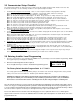
COLOR CODE for CAT5 or CAT6 Data Bus Cable
to RJ45 Plugs for ELK-M1DBH Data Bus Hub.
Pin1
Front
view
Optional programmable Zone Input from Keypad
Optional programmable Output from Keypad
Load (50mA max)
I.E. LED, Relay
-
+
To BLACK (Neg) Wire
To BROWN Wire
N.C
.
N.O
.
2200
Ohm
EOL
To BLACK (Neg) Wire
To BLUE Wire
BLUE
Keypad
Keypad
CAT5
or
CAT6
Cable
† Not evaluated by UL †† Not for use in UL Listed Systems