
Instruction Manual


13
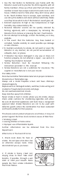
If necessary, it is possible to further secure the Detector by
using a 2-3mm (1/8”) diameter x 6-8mm (1/4”) long self
tapping screw (not supplied) to firmly lock the Detector and
its’ mounting plate together (see Figures 8c and 8d).
Attach the Detector to the mounting plate.
Line up the screw (not supplied) on the “U” shaped recessed
area shown in Figure 8c and install screw until fully secured.
To remove the Detector from the ceiling, remove the screw
first, and then twist off counterclockwise.
Your Detector is a life safety device and should be checked
periodically.
Manually Testing your Detectors
It is recommended that you test your Detectors after
installation and then at least weekly to ensure the units are
working. It will also help you and your family to become
familiar with the Detector alarming sound.
- Press and hold the Test Button until the Detector sounds
and the red LED flashes (see Figure 7). The Detector will
stop sounding shortly after the button is released.
- Repeat this procedure for all other Detectors in the system.
WARNING: Do not test with flame. This could set fire to
the Detector and damage the house. We do not recommend
testing with actual smoke as the results can be misleading
unless special apparatus is used.
When you press the Test button it simulates the effect of
smoke in a Smoke Detector which it could experience in a
real fire.
Test/Silence Button to Control Nuisance Detectors
The Smoke Detector has a combined Test/Silence button to
help you control nuisance/false detections.
When the Detector sounds if there is no sign of smoke or
noise to indicate that there is a fire, it should be assumed that
it is due to an actual fire, the dwelling should be evacuated
immediately and contact the local Fire Department.
It is possible that cooking smoke, steam, etc., may be the
source of a nuisance/false detection.
If there are frequent nuisance/false detection of alarms, it
may be necessary to re-locate the Detector away from the
source (cooking smoke, shower steam, etc.)
Figure 8c Figure 8d
6 to 8 mm
2 to 3 mm
SELF TAPPING
SCREW
TAMPERPROOF SCREW
8. Testing and Maintenance