
Cut Sheet

Instructions
ELK-PD9
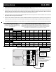
1. To remove the cover from the Power Distribution Module (ELK-PD9), use a small object like a screw driver to press into
the slots located on the end of the cover. Insure that the power switch is off.
2. Using Table 1 or Table 2 below, select an AC or DC Power Source that provides enough current to power the number of
devices to be used. The Power Source voltage must also match the device's voltage requirements. Mount the Power
Distribution Module near the Power Source that will be used to power the devices.
3. Connect the Power Source to the Power Distribution Module via the two Input Power Screw Terminals or the 2.1mm DC
jack(J1) located to the right of the terminals.
4. Connect a two conductor cable from the Power Distribution Module's Output terminals to the devices to be powered. If
desired, the total current draw can be measured at the Master Power Switch using an Ammeter while the switch is off.
5. Turn the Master Power Switch on, ensure all leds are on. Replace the plastic cover on the Power Distribution Module.
POWER DISTRIBUTION
9 OUTPUTS
PTCLED
LED
LED
LED
LED
LED
LED
LED
LED
POS
24VAC or
24VDC or
12VDC
NEG
PTC
PTC
PTC
PTC
PTC
PTC
PTC
PTC
POS NEG POS
POWER 1
NEG POS NEG
POWER 3POWER 2
POS NEG POS
POWER 4
NEG POS
POWER 6POWER 5
POS NEG POS
POWER 7
NEG POS
POWER 9POWER 8
NEG NEG
SW1
J1
CENTER
PIN +
OFF
ON
-
+
CONNECT INPUT
POWER HERE
12 or 24 VOLTS
AC or DC
(30 VOLTS MAX)*
TOTAL CURRENT DRAW CAN BE
MEASURED BY ATTACHING A
CURRENT METER TO THESE TEST
POINTS LOCATED ON SW1 LEADS
SW1 MUST BE TURNED OFF IN ORDER
TO MEASURE THE CURRENT
* WARNING! THE SIZE OF THE INPUT
POWER SOURCE MUST BE LARGER THAN
THE COMBINED TOTAL LOAD OF THE
ATTACHED DEVICES.
THE INPUT POWER SOURCE MUST ALSO
MATCH THE DEVICE'S OPERATING
VOLTAGE SPECIFICATIONS
OPTIONAL :
12 VOLT DC
PLUG-IN
POWER
SUPPLY
CONNECT DEVICES TO BE
POWERED TO THESE
TERMINALS
Observe Polarity
if using DC Voltage
Figure 2: Power Distribution Module(ELK-PD9)
Model #
Voltage
Output
Amps VA / Watts
Table 2: Quick Power Supply Selection by Number of Devices
Select a column that closely approximates the power consumption of each device. For the
desired voltage, select the row that meets or exceeds the number of desired devices. The
appropriate Power Supply Model # is shown at left. NOTE: If a device consumes more than the
max. rating of a single PD9 output then parallel two or more outputs together to achieve the
desired capacity. Use additional PD-9's for every 9 devices or as required.
@200mA
(2.4W)
@100mA
(1.2W)
@75mA
(.9W)
Max. Available Power
@150mA
(1.8W)
@125mA
(1.5W)
@175mA
(2.1W)
@200mA
(4.8W)
@100mA
(2.4W)
@75mA
(1.8W)
@150mA
(3.6W)
@125mA
(3W)
@175mA
(4.2W)
@225mA
(2.7W)
@225mA
(5.4W)
Table 1: Sizing the Power Supply
Calculate the total combined power consumption of
all devices. Select a Power Supply which has a
Max. Available Power capacity that meets or exceeds
the calculated total.
Model #
Voltage
Output
Current VA / Watts
Max. Available Power
ELK-624 12 VDC 1 A 12
ELK-P1216 12 VDC 1.5A 18
5 10 136 854
7 15 2010 1286
ELK-624 24 VDC .8A 19
ELK-T2440 24 VAC 1.7A 40
4 8 105 643
8 17 2110 1297
ELK-PD9
ELK-PD9HC
@300mA
(3.6Watts)
@125mA
(1.5Watts)
@100mA
(1.2Watts)
@200mA
(2.4Watts)
@150mA
(1.8Watts)
@250mA
(3Watts)
@400mA
(4.8Watts)
Model #
Voltage
Output
Amps VA / Watts
Max. Available Power
ELK-P412 12 VDC 4A 48 13 32 4020 261610
ELK-P412 12 VDC 4A 48 20 40 5326 322217
07/04