
User Manual


ELKA SUSPENSION INC. Phone: (450) 655-4855 or 1 800 557-0552 www.elkasuspension.com 5
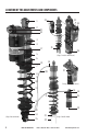
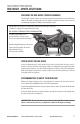
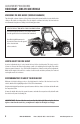
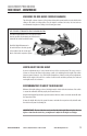
LOCATION OF THE ADJUSTMENTS AND COMPONENTS
1. Top mounting eyelet, featuring spherical bearing
2. Head of the shock absorber
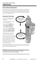
3. PRELOAD adjustment ring (see p.10 for adjustment procedures)
4. Self-sagging spring (no-preload), will normally compress from the weight of the vehicle
5. Top crossover spacer, prevents coil binding of the self-sagging spring
6. Middle spring, vehicle-specific to control body roll
7. CROSSOVER SPACER, controls the initial firmness or softness
8. Body of the shock absorber
9. Triple-seal seal head of the shock absorber
10. Main spring, specific for the rider’s weight
11. Shaft
12. Bottom-out bumper
13. Heavy-duty spring clip
14. REBOUND adjuster (knob type, see p.14 for adjustment procedures)
15. Lower mounting eyelet, featuring spherical bearing
16. COMPRESSION adjuster (see p.11 for adjustment procedures)
17. Reservoir (piggyback type)
18. Banjo bolt fitting
19. Nitrogen purge valve, NOT AN ADJUSTMENT
20. Hose
21. REBOUND adjuster (compact type, see p.14 for adjustment procedures)
22. Lower mounting fork
23. LOW-SPEED COMPRESSION adjuster (red knob, see p.12 for adjustment procedures)
24. HIGH-SPEED COMPRESSION adjuster (black knob, see p.13 for adjustment procedures)
25. Reservoir (remote type), length may vary from one vehicle to another
26. Composite Shock Protector (optional on some models)
27. Patented TRACK System
™
adjustment knob (see p.15 for adjustment procedures)