
Installation


Page 6
1000005817
1000005818 (Rev. A - 06/20)
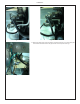
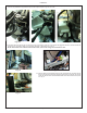
22. Connect the black wire from the kit. The female connector is connection on the wire is connected to the piggyback terminal on the cold control and
the other end is connected to either one of the empty terminals on the solenoid. Fig. 15 & 16
NOTE: Some models have a dierent solenoid and location, however the wiring process remains the same.
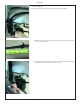
23. Place the basin shroud assembly back on to the cooler frame and connect the sensor
wires. Connect the black wire to the piggyback terminal on the solenoid, the red wire
on the open terminal on the solenoid and the white wire to the white wire on the power
cord. Fig. 17
Fig. 17
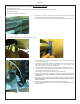
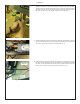
21. Replace the cover over the compressor electricals. Place the slot on the cap on the lower arm on the compressor, slide all the wire into the large
slot in the cap. Rotate the cap upwards and push until it snaps into place. Fig. 14a, 14b & 14c
Fig. 14a Fig. 14b Fig. 14c
Fig. 15 Fig. 16