
Installation


PAGE 21000004231 (Rev. B - 01/18)
4410_FTN_A LK4410_FTN_A
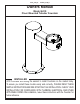
1. This fountain is to be mounted on a smooth, at, nished surface with adequate support structure.
NOTE: Mounting structure must be capable of supporting 300 lb. load minimum on fountain.
2. Refer to rough-in for plumbing.
3. Install shut-off valve on water supply. (Valve not furnished)
4. Locate and install fountain using 3/8" minimum fasteners. (Fasteners not furnished)
5. Connect water supply and fountain drain. Water connection and drain must comply with local codes.
6. Turn on water supply and check all connections for leaks.
CAUTION: This fountain is rated for inlet water pressure of 20-105 PSI. A pressure reducing regulator should be used if the
inlet water supply exceeds 105 PSI. Any damage caused by reason of connecting this product to supply line
pressures lower than 20 PSI or higher than 105 PSI is not covered by warranty.
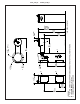
7. Water supply 3/8" O.D. unplated copper tube. Waste 1-1/4" IPS. Contractor to supply waste trap and service stop valve in
accordance with local code.
8. Connecting lines to be made of unplated copper and should be thoroughly ushed to remove all foreign matter before being
connected to fountain. This fountain is manufactured in such a manner that it does not in any way cause taste, odor, color,
or sediment problems.
9. Connect fountain to supply line with a shut-off valve and install a 3/8" unplated copper water line between the valve and the
fountain. Remove any burrs from outside of water line. Push the tubes straight into the ttings until they reach a positive
stop, approximately 3/4" (See Fig. 2). DO NOT SOLDER TUBES INSERTED INTO THE STRAINER AS DAMAGE TO THE
O-RINGS MAY RESULT.
INSTALLATION INSTRUCTIONS
IMPORTANT
ALL SERVICE TO BE PERFORMED BY AN AUTHORIZED SERVICE PERSON
IMPORTANT! INSTALLER PLEASE NOTE.
THE GROUNDING OF ELECTRICAL EQUIPMENT SUCH AS TELEPHONE, COMPUTERS, ETC. TO WATER LINES
IS A COMMON PROCEDURE. THIS GROUNDING MAY BE IN THE BUILDING OR MAY OCCUR AWAY FROM THE
BUILDING. THIS GROUNDING CAN CAUSE ELECTRICAL FEEDBACK INTO A FOUNTAIN, CREATING AN
ELECTROLYSIS WHICH CAUSES A METALLIC TASTE OR AN INCREASE IN THE METAL CONTENT OF THE
WATER. THIS CONDITION IS AVOIDABLE BY USING THE PROPER MATERIALS AS INDICATED. ANY DRAIN
FITTINGS PROVIDED BY THE INSTALLER SHOULD BE MADE OF PLASTIC TO ELECTRICALLY ISOLATE THE
FOUNTAIN FROM THE BUILDING PLUMBING SYSTEM.
TROUBLE SHOOTING AND MAINTENANCE
ACTUATION OF QUICK CONNECT WATER FITTINGS:
Fountain is provided with lead-free connectors which utilize an o-ring water seal. To remove tubing from the tting, relieve
water pressure, push in on the gray collar while pulling on the tubing. (see Fig.2) To insert tubing, push tube straight into
tting until it reaches a positive stop, approximately 3/4".
B CA
SIMPLY PUSH IN
TUBE TO ATTACH
TUBE IS SECURED
IN POSITION
PUSH IN COLLET
TO RELEASE TUBE
OPERATION OF QUICK CONNECT FITTINGS
PUSHING TUBE IN BEFORE
PULLING IT OUT HELPS TO
RELEASE TUBE
OPERATION OF QUICK CONNECT FITTINGS
SIMPLY PUSH IN
TUBE TO ATTACH
TUBE IS SECURED
IN POSITION
PUSH IN COLLET
TO RELEASE TUBE
PUSHING TUBE IN BEFORE
PULLING IT OUT HELPS TO
RELEASE TUBE
A B C
1/4” O.D. TUBE
WATER INLET
TO COOLER
3/8” O.D. TUBE CONNECT
COLD WATER SUPPLY
BUILDING WATER
INLET
NOTE: WATERFLOW
DIRECTION
SERVICE STOP
(NOT FURNISHED)
FIG 1 FIG 2