
Installation Instructions

FOR PARTS, CONTACT YOUR LOCAL DISTRIBUTOR OR CALL 1.800.323.0620
97153C (Rev. F - 8/11)
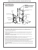
5/16" SCREWS OR BOLTS
(12 REQ'D-NOT FURNISHED)
FRAME
5/16" HEX NUT
(4 REQ'D - PROVIDED)
P/N 111577343890
SCREWS OR BOLTS
(NOT PROVIDED)
BOLT FRAMES TOGETHER
WITH 5/16" X 3/4" (19mm) BOLTS
(4 REQ'D- PROVIDED)
P/N 111577243890
37 3/4"
959mm
4 1/2"
14mm
37 1/2"
953mm
5 1/8"
130mm
8"
203mm
1 1/8"
29mm
TO FLOOR LINE
BACK OF WALL
TO BE 12"
(305mm) MIN
DEPTH
FLOOR LINE
WOOD OR STEEL FRAME
SHOWN (NOT PROVIDED)
ELECTRICAL INLET
LOCATION ON
CHILLER
INSTALL (3) SCREWS
(P/N 111008343890) IN FRAME
BEFORE INSTALLING IN OPENING
HOOK RODS (2)
P/N 101567443730
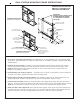
IMPORTANT:
DOUBLE STUD OR 3 INCHES (76mm)
BETWEEN MOUNTING FRAMES
IF PLACED NEXT TO A BOTTLE
FILLER UNIT
1. Cut a square rectangular wall opening 37 1/2" (953mm) W x 37 3/4" (959mm) H and 4 1/2" (114mm) above
the floor line. These dimensions are required to obtain proper rim and bubbler heights for compliance with ANSI
standard A117.1.
2. Reinforce the wall opening on all sides so that it will adequately support the water fountain. This reinforce
ment must support up to 150 lbs static load and provide a means for securing the frame assembly in place.
NOTE: Building construction must allow for adequate air flow on both sides and top of remote chiller unit.
Minimum of 4" (102mm) is required.
3. Install plumbing and electrical rough-ins. A junction box for a (3) wire, 10 amp branch circuit is provided on
the inside of the chiller. (Standard 120 Volts, 60 Hz and single phase)
4. Remove frame assembly and related hardware from packaging. Attach the two frames together thru the
upright supports with (4) 5/16" x 3/4" (19mm) long bolts and nuts (provided). Tighten securely.
5. Install the frame assembly squarely in wall opening with frame upright support edges flush with the finished
wall face. Secure the frame to the wall thru holes with (12) 5/16" bolts or screws (not provided). Tighten securely.
NOTE: Be sure that frame is squared in location. Do not use less than required screw quantity and size.
6. Attach the chiller shelf support rods to the right side frame uprights at the second set of holes counting from
the bottom and to the shelf at the (2) side holes. Line up the other shelf holes with the frame bottom holes and
fasten the assembly to the wall using appropriately sized screws or bolts and nuts (not provided).
DUAL-STATION MOUNTING FRAME INSTRUCTIONS
REVERSED CONFIGURATION:
HIGHER UNIT ON THE RIGHT
STANDARD CONFIGURATION:
HIGHER UNIT ON THE LEFT
ACTUAL FRAME MAY VARY
FROM THE ONE ILLUSTRATED.
REFER TO YOUR MODEL FOR
ADDITIONAL INFORMATION.