
Installation Instructions

97866C (Rev. K - 1/12)
ECRSP8C*A ECRSPVR8C*A LCRSP8C*A
PAGE 3
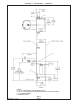
FIG. 7
ECRSP8C
TUBE ROUTING
INSTALLATION INSTRUCTIONS
1. Install remote chiller. Remove front panel of chiller. Remove and discard cardboard inner pack from between compressor and
side panel. Slide chiller onto the shelf and position it to the left within the guides on the shelf.
NOTE: Building construction must allow for adequate air flow on both sides, top, and back of chiller. See chiller instructions for
additional instructions.
2. Make water supply connections. Install a shut-off valve and union connection to building water supply (valve and union not
provided). Turn on the water supply and flush the line thoroughly.
3. ECRSP MODELS: Make connection between remote chiller and building supply line. Inlet port is marked on the chiller (1/4" O.D.
copper tube). Bend the copper tube (provided) at an appropriate length from chiller to opening in frame. Install the in-line strainer
(provided with chiller) by pushing it in until it reachs a positive stop, approximately 3/4" (19mm) on the marked chiller inlet port.
Connect building supply line to strainer. DO NOT SOLDER TUBES INSERTED INTO THE STRAINER AS DAMAGE TO THE O-
RINGS MAY RESULT. (See Figure 7)
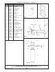
LCRSP MODEL: Mount filter head assembly to side of chiller (See Figure 9). Make connection between filter and building supply
line (3/8" O.D. tube not provided). Inlet port is marked on the chiller (1/4" O.D. copper tube). Install a 1/4" x 1/4" union (provided)
on the marked chiller inlet port. Insert the 1/4" poly tubing (provided) into fitting on filter and connect to the union on the chiller. DO
NOT SOLDER TUBES INSERTED INTO THE UNIONS AS DAMAGE TO THE O-RINGS MAY RESULT. (See Figure 8).
4. Hang the upper panel on the mounting frame hanger. Align holes in the panel with the holes in the mounting frame. Be sure that
panel is engaged with hanger at top of frame before releasing it.
5. Install the fountain. Remove access cover plate on underside of fountains and save the screws. Mount the fountain to the
upper panel and the wall frame with (4) 5/16" x 3/4" (19mm) long bolts and nuts (provided). Tighten securely.
6. Insert waste tube (provided) into drain on fountain. Attach waste tube (1 1/4" OD) to 1 1/4" OD slip trap (provided by others).
7. ECRSP MODELS: Make connections between remote chiller outlet tube and fountain. Outlet port is marked on the chiller
(1/4" O.D. copper tube). Install a 1/4" x 1/4" union (provided) on the marked chiller outlet port. Insert the 1/4" poly tubing coming
from the fountain into the union. Turn on water supply and check for leaks. DO NOT SOLDER TUBES INSERTED INTO THE
UNIONS AS DAMAGE TO THE O-RINGS MAY RESULT. (See Figure 7).
LCRSP MODEL: Make connections between remote chiller and fountain. Outlet port is marked on the chiller (1/4" O.D. copper
tube). Install a 1/4" x 1/4" union (provided) on the marked chiller outlet port. Insert the 1/4" poly tubing coming from the fountain
into the union. Turn on water supply and check for leaks. DO NOT SOLDER TUBES INSERTED INTO THE UNIONS AS DAMAGE
TO THE O-RINGS MAY RESULT. (See Figure 8).
8. These products are designed to operate on 20-105 PSIG supply line pressure. If inlet pressure is above 105 PSIG, a pressure
regulator must be installed in the supply line. Any damage caused by reason of connecting these products to supply line
pressures lower than 20 PSIG or higher than 105 PSIG is not covered by warranty.
9. Make electrical connections to the chiller. See chiller instructions.
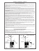
10. Check stream height from bubbler. Stream height is factory set at 35 PSI. If supply pressure varies greatly from this, adjust the
screw on regulator item 10 by using a small screwdriver through the small hole in the push button item 3 (See Fig.3). Clockwise
adjustment will raise stream height and counter-clockwise will lower stream height. For best adjustment stream should hit basin
approximately 6 1/2" from the bubbler.
11. Mount lower panel. Loosen the (2) #10-24 x 5/8" (16mm) screws at frame bottom lip. Slide upper tongue of lower panel under
lower edge of already installed upper panel. Tighten previously loosened screws securely.
12. Replace bottom access panel to fountain basin using screws provided. Tighten securely.
TROUBLE SHOOTING AND MAINTENANCE
1. Orifice Assy: Mineral deposits on orifice can cause water flow to spurt or not regulate. Mineral deposits may be removed
from orifice with a small round file not over 1/8" diameter or a small diameter wire.
CAUTION: Do not file or cut orifice materials.
2. Stream Regulator: If orifice is free of material deposits, regulate flow according to instruction 10 stated above.
3. Actuation of Quick Connect Water Fittings: Cooler is provided with lead-free connectors which utilize an o-ring water
seal. To remove tubing from the fitting, relieve water pressure, push in on the gray collar while pulling on the tubing (See Fig. 2)
To insert tubing, push tube straight into the fitting until it reaches a positive stop, approximately 3/4".
CHILLER
OUTLET
25
13
TO BUBBLER
TO BUBBLER
WATER
INLET
CHILLER
OUTLET
25
25
LCRSP8C TUBE ROUTING
FIG. 8
CHILLER
INLET
33
33
33
33
33