
Specification Sheet

28-3/8"
(721mm)
11"
(279mm)
1-1/8"
(29mm)
5-1/2"
(140mm)
3-1/2"
(89mm)
4-1/2"
(114mm)
1"
(25mm)
25-3/16"
(640mm)
12"
(305mm)
MINIMUM
DEPTH
18"
(457mm)
24"*
(610mm)
CHILD ADA
REQUIREMENT
3-1/8"
(80mm)
1-1/8"
(29mm)
9-3/8"
(238mm)
8-1/8"
(206mm)
FINISHED FLOOR
WALL LINE
BACK
WALL
LINE
1-1/4" (32mm)
DRAIN TUBE
FURNISHED
ELECTRICAL
INLET
18-15/16"
(481mm)
12-1/8"
(308mm)
19-3/4"
(502mm)
3-13/16"
(97mm)
3-13/16"
(97mm)
21-7/8"
(556mm)
*27" (686mm) FOR ADULT ADA
ADJUST OTHER MEASUREMENTS ACCORDINGLY
3/8" O.D. TUBE CONNECT
(CHILLER WATER INLET)
SHUT OFF VALVE BY OTHERS
1/4" O.D. TUBE CONNECT
(CHILLER WATER OUTLET)
HOOK RODS (2)
P/N 101567443730
INSTALL (3) SCREWS
(P/N 111008343890)
IN FRAME BEFORE
INSTALLING IN OPENING
ELECTRICAL INLET
LOCATION ON
CHILLER
WOOD OR STEEL FRAME
SHOWN (NOT PROVIDED)
FLOOR LINE
BACK OF
WALL TO BE
12" (305mm)
MIN. DEPTH
TO FLOOR LINE
1-1/8"
(29mm)
8"
(203mm)
5-1/8"
(130mm)
37-1/2"
(953mm)
4-1/2"
(14mm)
37-3/4"
(959mm)
BOLT FRAMES TOGETHER
WITH 5/16" X 3/4" (19mm) BOLTS
(4 REQ'D- PROVIDED)
P/N 111577243890
SCREWS OR BOLTS
(NOT PROVIDED)
5/16" HEX NUT
(4 REQ'D - PROVIDED)
P/N 111577343890
FRAME
5/16" SCREWS OR BOLTS
(12 REQ'D- NOT FURNISHED)
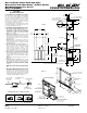
ECRSPM8K MOUNTING FRAME INSTRUCTIONS
1. Cut a square rectangular wall opening
37-1/2"
(953mm) W x 37-3/4" (959mm) H and 4-1/2"
(114mm) above the floor line. These dimensions
are required to obtain proper rim and bubbler
heights for compliance with ANSI standard
A117.1. (See Figure 2)
2. Reinforce the wall opening on all sides so that it
will adequately support the water fountain. This
reinforcement must support up to 150 lbs static
load and provide a means for securing the frame
assembly in place.
NOTE: Building construction must allow for
adequate air flow on both sides and top of remote
chiller unit. Minimum of 4" (102mm) is required.
(See Figures 1 & 2)
3. Install plumbing and electrical rough-ins. See
Figure 1 for location of the supply water inlet to
chiller and for the location of the waste water
outlet. A junction box for a (3) wire, 10 amp
branch circuit is provided on the inside of the
chiller. (Standard 120 Volts, 60 Hz and single
phase) See Figure 2 for the electrical inlet location.
4. Remove frame assembly and related hardware
from packaging. Attach the two frames together
thru the upright supports with (4) 5/16" x 3/4"
(19mm) long bolts and nuts (provided). Tighten
securely.
NOTE: Frame with higher upper channel to be on
right side.
5. Install the frame assembly squarely in wall
opening with frame upright support edges flush
with the finished wall face. Secure the frame to
the wall thru holes with (12) 5/16" x 2" (51mm)
long lag bolts or screws (not provided). Tighten
securely.
NOTE: Be sure that frame is squared in location.
Do not use less than required screw quantity and
size.
6. Attach the chiller shelf support rods to the right
side frame uprights at the second set of holes
counting from the bottom and to the shelf at the
(2) side holes. Line up the other shelf holes with
the frame bottom holes and fasten the assembly
to the wall using appropriately sized wood screws
or bolts and nuts (provided). (See Figure 2)
FIG.1
FIG. 2
IMPORTANT!
INSTALLER PLEASE NOTE:
The grounding of electrical equipment such as tele-
phone, computers, etc., to water lines is a common
procedure. This grounding may be in the building or
may occur away from the building. This grounding
can cause electrical feedback into a water cooler,
creating an electrolysis which creates a metallic
taste or causes an increase in the metal content of
the water. This condition is avoidable by using the
proper materials as indicated below.
The drain fittings which are provided by the installer
should also be plastic to electrically isolate the cooler
from the building plumbing system.
Elkay
2222 Camden Court
Oak Brook, IL 60523
elkayusa.com
Printed in U.S.A.
©2006 Elkay
12-39A (Rev. 7/06)
NOTE: WATERFLOW
DIRECTION
SERVICE STOP
(NOT FURNISHED)
3/8" O.D. TUBE CONNECT
COLD WATER SUPPLY
BY OTHERS
1/4" O.D. TUBE
WATER INLET
TO COOLER
BUILDING WATER
INLET
OPERATION OF QUICK CONNECT FITTINGS
SIMPLY PUSH IN
TUBE TO ATTACH
TUBE IS SECURED
IN POSITION
PUSH IN COLLET
TO RELEASE TUBE
PUSHING TUBE IN BEFORE
PULLING IT OUT HELPS TO
RELEASE TUBE
AB
C
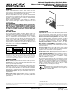
No Lead Single Station Child Soft Sides
®
Water Cooler with WaterSentry
®
VII Filter System
Wall Mount Barrier-Free Access
Model ECRSPM8K
®
ROUGH-IN DIMENSIONS