
Installation Guide

97156C (Rev. S - 3/13)
EDFP210C*B EDFP214C*B EDFPVR214C*B EDFP217C*B
PAGE 4
FOR PARTS, CONTACT YOUR LOCAL DISTRIBUTOR OR CALL 1.800.323.0620
ELKAY MANUFACTURING COMPANY • 2222 CAMDEN COURT • OAK BROOK, IL 60523 • 630.574.8484
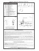
PART NO.ITEM NO.
PARTS LIST
DRAIN
RETAINING NUT
PUSH BUTTON
PUSH BUTTON SLEEVE
REGULATOR HOLDER
ORIFICE ASSY
HOUSING ASSY
PEDESTAL
BUBBLER LOCKNUT
REGULATOR
SCREW -CAP #6-32 X 5/16
SCREW - #10-24 X .50 PHTC
STRAINER
FOUNTAIN ARM - SHORT
FOUNTAIN ARM - LONG
FOUNTAIN ARM - LONG (GLASSFILLER)
BOTTOM COVER PLATE - SHORT
BOTTOM COVER PLATE - LONG
BACK PANEL ASSY - EDFP217C
HEX NUT
REGULATOR MOUNTING BRACKET
KIT - BUBBLER (VR)
POLY TUBING (CUT TO LENGTH)
EDGE TRIM - 2FT.
TEE - 1/4
LK464
15005C
45662C
45663C
50986C
A54874
56011C
55997C
75580C
61313C
75672C
112627543890
55996C
28782C
28783C
27959C
55000661
55000665
27121C
40045C
28823C
70892C
56092C
56369C
70682C
1
2
3
4
5
6
7
8
9
10
11
12
13
14
15
16
17
18
19
20
21
NS
DESCRIPTION
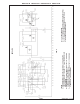
FIG. 8
NOTE: WHEN INSTALLING REPLACEMENT
BUBBLER AND PEDESTAL, TIGHTEN NUT
(ITEM 9 OR 21) ONLY TO HOLD PARTS SNUG
IN POSITION. DO NOT OVER TIGHTEN.
FIG. 6
17
2
10
5
3
4
18
11
14
SEE FIG. 6 OR 7
16
SEE
FIG. 5
12, 15
1
13
INSTALLATION INSTRUCTIONS
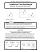
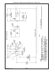
1. Wall should already be framed for the fountain using the positioning dimensions shown in Figures 3 or 4. Shown dimensions pertain to
installation location (framing must support up to 150 lbs. weight). These dimensions are required for compliance with ANSI Standard A117.0.
2. Install rough-in plumbing as shown in Figures 3 or 4. Waste line should extend a minimum of 2" (51mm) through the back panel. Run the
supply water inlet line through the back panel. Install a service stop (not provided). Turn on supply water and flush thoroughly.
3. Remove bottom access panel from fountain basin and save the screws. Install the fountain to the back panel and wall using (4) 5/16" x 2" long
lag bolts and washers (not provided) through holes in back panel. Tighten securely.
4. Remove elbow from end of p-trap and attach it to drain tube. Reattach elbow to p-trap and cut waste tube to required length using plumbing
hardware and trap as a guide.
5. Make water supply connections from service stop to the 3/8" O.D. unplated copper tube coming out of the strainer. Turn on water supply and
check for leaks. Newly installed water supply line should be insulated after leak check is completed. DO NOT SOLDER TUBES INSERTED
INTO THE STRAINER AS DAMAGE TO THE O-RINGS MAY RESULT.
6. These products are designed to operate on 20-105 PSIG supply line pressure. If inlet pressure is above 105 PSIG, a pressure regulator must be
installed in the supply line. Any damage caused by reason of connecting these products to supply line pressures lower than 20 PSIG or higher
than 105 PSIG is not covered by warranty.
7. Check stream height from bubbler. Stream height is factory set at 35 PSI. If supply pressure varies greatly from this, adjust the screw on
the regulator (Item 10) by using a small screw driver through the small hole in the push button (Item 3). Clockwise adjustment will raise stream
height and counter-clockwise will lower stream height. For best adjustment stream should hit basin approximately 6-1/2" (165mm) from bubbler.
8. Replace bottom access panel to fountain using the screws provided. Tighten securely.
TROUBLE SHOOTING AND MAINTENANCE
1. Orifice Assy: Mineral deposits on orifice can cause water flow to spurt or not regulate. Mineral deposits may be removed from orifice with a
small round file not over 1/8" diameter or a small diameter wire.
CAUTION: Do not file or cut orifice materials.
2. Stream Regulator: If orifice is free of material deposits, regulate flow according to instruction 7 stated above.
3. Actuation of Quick Connect Water Fittings: Cooler is provided with lead-free connectors which utilize an o-ring water seal. To remove tubing
from the fitting, relieve water pressure, push in on the gray collar while pulling on the tubing (See Figure 2). To insert tubing, push tube straight
into the fitting until it reaches a positive stop, approximately 3/4".
7
8
9
6
FIG. 5
FIG. 7
20
21
19