
Installation Guide

Page 9
EDFPB117C, EDFPBM117C, EDFPB117RAC, EDFPBM117RAC, EDFPBV117C,
EDFPBMV117C, EDFPBV117RAC, EBFPBMV117RAC
97922C (Rev. G - 6/08)
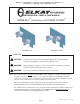
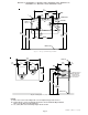
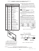
Figure 17 – Water Supply Connections
NOTE: WATER FLOW
DIRECTION
SERVICE STOP
(NOT FURNISHED)
BUILDING WATER INLET
3/8" O.D. UNPLATED
COPPER TUBE CONNECT
COLD WATER SUPPLY
1/4" O.D. TUBE
WATER INLET
TO COOLER
TROUBLESHOOTING & MAINTENANCE
Orifice Assembly: Mineral deposits on orifice
can cause water flow to spurt or not regulate. Mineral
deposits may be removed from the orifice by poking
with a small round file not over 1/8” diameter, or using a
small diameter wire.
!
CAUTION
:
DO NOT file or cut orifice
material.
Stream Regulator: If orifice is clean, regulate
flow as in Step 8 of the installation instructions. If
replacement is necessary, see parts list for correct
regulator part number.
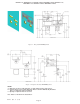
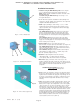
Actuation of Quick Connect Water
Fittings: Cooler is provided with lead-free connec-
tors which utilize an o-ring water seal. To remove
tubing from the fitting, relieve water pressure, push in
on the gray collar while pulling on the tubing. (See
Figure 15) To insert tubing, push tube straight into
fitting until it reaches a positive stop (approximately 3/4”).
Figure 15 – Quick Connect Fittings
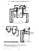
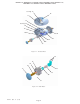
PARTS LIST
ITEM NO.
PART NO.
DESCRIPTION
1
2
3
4
5
6
7
8
9
10
11
12
13
14
15
16
17
18
19
20
21
22
23
24
25
26
27
28
29
30
31
32
33
34
35
NS
56073C
40319C
50171C
50314C
56011C
55997C
75580C
98118C
100322740560
15009C
28474C
28473C
45767C
28343C
45781C
45847C
45848C
50986C
61313C
15005C
56163C
45769C
45768C
56092C
28392C
28393C
AP99
111008343890
70432C
38417001
75560C
75632C
70817C
55996C
75671C
28844C
28845C
27090C
Bubbler Assy
Fitting - Orifice
O-Ring
Orifice - Flow Straightener
Housing Assembly
Pedestal
Bubbler Locknut
Bubbler Assembly VR
Gasket - Black .68 x 1.03 VR
Nipple - Bubbler VR
Basin - Swirlflow
Lower Shell
Fountain Body
Cover Plate
Sleeve
Pin - Push Button
Push Button
Holder - Regulator
Regulator
Retaining Nut
Gasket - Drain
Assy - Drain/Tailpipe
Drain - Plug 1-1/2”
Poly Tubing (Cut To Length)
Back Panel RH ADA
Back Panel LH ADA
AP-99 Panel (Optional)
Screw - #10-24 x .62 HHMS
Screw - #8-32 x .38 THSM
Screw - #8-18 x .37 HHSM
Screw - 5/16-18 x 1.00 HHMS
Setscrew - #10-32 x .31
Fttng - Elbow 1/4 x 1/4
Strainer
Spring - Push Button
Back Panel Assy RH ADA
Back Panel Assy LH ADA
Hanger Bracket
FOR PARTS, CONTACT YOUR LOCAL DISTRIBUTOR OR CALL 1.800.323.0620
ELKAY MANUFACTURING COMPANY · 2222 CAMDEN COURT · OAK BROOK, IL 60523 · 630.574.8484
PRINTED IN U.S.A.
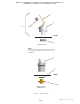
33
35
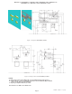
Installing Back Panel: When installing back panel
assy. (Item 35) with MPW (Mounting Plate), attach
channel braces as shown above. Remove the
protective backing from the tape installed on the
braces. Line up the corresponding holes in the
braces and back panel and press firmly in place.
Figure 16 – Back Panel Assembly