
Use and Care Manual

Page 6
EDFPB117C, EDFPBM117C, EDFPB117RAC, EDFPBM117RAC, EDFPBV117C,
EDFPBMV117C, EDFPBV117RAC, EBFPBMV117RAC
97922C (Rev. H - 01/18)
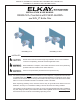
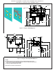
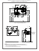
Figure 9 -Panel Installation
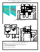
Figure 10 - Fountain Installation
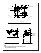
Figure 11 - AP-99 Panel (Optional)
6
9
Installation Instructions:
1. Fountains using the MPW Mounting Plate refer to Figures
5 or 7 for hanger bracket location and rough-in dimensions.
NOTE: Review separate installation instructions for details of the
MPW Mounting Plate.
Fountains using the Wall Plate Assy. refer to Fig’s. 1 or 3
for rough-in dimensions.
2. Shown dimensions pertain to installation location (framing must
support up to 300 lbs. weight). These dimensions are required for
compliance with ANSI Standard A117.0.
3. Install rough-in plumbing as shown in Fig’s. 1, 3, 5, or 7. Run
supply water inlet line through the back panel. Install a service
stop (not provided). Turn on supply water and ush thoroughly.
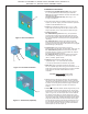
4. Installing back panel.
Ftn. w/MPW Mounting Plate: Refer to Fig. 16 for placement
of braces onto back panel. Place the upper edge of the panel
above the hanger bracket. Slide the panel down until it engages
the hanger bracket. Be sure back panel is rmly engaged before
releasing it.
Ftn. w/Wall Plate Assy.: Place the upper edge of the panel
above mounting plate on the wall. Slide the panel down until it
engages the mounting plate. Be sure back panel is rmly engaged
before releasing it. (See Figure 9)
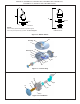
5. Install fountain. Remove screw (Item 9) from cover
plate and slide cover plate (Item 14) toward basin. (See Figure 10)
Ftn. w/MPW Mounting Plate: Mount the fountain to the back
panel and wall using (4) 5/16” x 6” long threaded rods, washers,
and nuts (provided). Tighten securely.
Ftn. w/Wall Plate Assy.: Mount the fountain to the back panel
and wall plate assy. with (4) 5/16” x 1” (25mm) long screws
(Item 6 - provided). Tighten securely.
6. Determine required length of waste line and cut to
appropriate length. 1-1/4” O.D. waste tube furnished.
1-1/4” slip trap, waste elbow and extension not provided.
7. Make water supply connections from service stop to the
3/8” O.D. unplated copper tube coming out of the strainer. Turn on
water supply and check for leaks (See Figure 17). Newly installed
water supply line should be insulated after leak check is
completed.
CAUTION: DO NOT SOLDER tubes inserted
into the strainer as damage to the
o-rings may result.
8. These products are designed to operate on 20-105 PSI supply
line pressure. If the inlet pressure is above 105 PSI, a pressure
regulator must be installed in the supply line. Any damage caused
by reason of connecting these products to supply line pressures
lower than 20 PSI or higher than 105 PSI is not covered by
warranty.
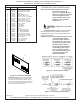
9. Check stream height from bubbler. Stream height is factory set at
35 PSI. If supply pressure varies greatly from this, remove push
button (Item 17 - Figure 14) and adjust the screw on the regulator
(Item 19 - Figure 14). To remove push button, remove setscrew
from bottom of sleeve (Item 15). Insert a small punch in screw
hole and push up while grasping the push button and pull forward
removing the push button. Clockwise adjustment will raise stream
height and counterclockwise movement will lower stream height.
For best adjustment stream should hit basin approximately 6-1/2”
from the bubbler. Reassemble the push button by pushing in on
button until the push button catches in the sleeve. Reinstall the
setscrew (Item 5) in the sleeve (Item 15).
19
17
14