
Use and Care Manual

Page 8
EDFPB117C, EDFPBM117C, EDFPB117RAC, EDFPBM117RAC, EDFPBV117C,
EDFPBMV117C, EDFPBV117RAC, EBFPBMV117RAC
97922C (Rev. H - 01/18)
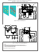
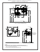
Figure 17 – Water Supply Connections
TROUBLESHOOTING & MAINTENANCE
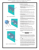
Orice Assembly: Mineral deposits on orice
can cause water ow to
spurt or not regulate. Mineral
deposits may be removed from
the orice by poking with a
small round le not over 1/8”
diameter, or using a small
diameter wire.
DO NOT le or cut orice
material.
Stream Regulator: If orice is clean, regulate
ow as in Step 8 of the installation instructions. If
replacement is necessary, see parts list for correct
regulator part number.
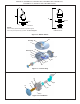
Actuation of Quick Connect Water Fittings: Cooler
is provided with lead-free
connectors which utilize an
o-ring water seal. To remove
tubing from the tting, relieve
water pressure, push in on
the gray collar while pulling
on the tubing. (See Figure
15) To insert tubing, push
tube straight into tting until
it reaches a positive stop
(approximately 3/4”).
Figure 15 – Quick Connect Fittings
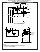
PARTS LIST
ITEM NO.
PART NO.
DESCRIPTION
1
2
3
4
5
6
7
8
9
10
11
12
13
14
15
16
17
18
19
20
21
22
23
NS
56073C
28844C
28845C
55996C
70817C
75632C
75560C
38417001
98118C
70432C
111008343890
28708C
28473C
45767C
28343C
45781C
98871C
AP99
98530C
28844C
28845C
56092C
56163C
0000000930
45768C
27090C
Bubbler Assy
Back Panel Assy RH ADA
Back Panel Assy LH ADA
Strainer
Fttng - Elbow 1/4 x 1/4
Setscrew - #10-32 x .31
Screw - 5/16-18 x 1.00 HHMS
Screw - #8-18 x .37 HHSM
Bubbler Assembly VR
Screw - #8-32 x .38 THSM
Screw - #10-24 x .62 HHMS
Basin - Swirlow
Lower Shell
Fountain Body
Cover Plate
Sleeve
Kit - Pushbutton/Spring/
AP-99 Panel (Optional)
Kit - Regular/Holder/Nut
Back Panel Assy RH ADA
Back Panel Assy LH ADA
Poly Tubing (Cut To Length)
Gasket - Drain
Assy - Drain/Tailpipe
Drain - Plug 1-1/2”
Hanger Bracket
FOR PARTS, CONTACT YOUR LOCAL DISTRIBUTOR OR CALL 1.800.834.4816
ELKAY MANUFACTURING COMPANY · 2222 CAMDEN COURT · OAK BROOK, IL 60523 · 630.574.8484 • www.elkay.com
PRINTED IN U.S.A.
3
2
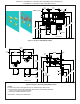
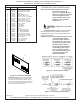
Installing Back Panel: When installing back panel
assy. (Item 2) with MPW (Mounting Plate), attach
channel braces as shown above. Remove the pro-
tective backing from the tape installed on the braces.
Line up the corresponding holes in the braces and
back panel and press rmly in place.
Figure 16 – Back Panel Assembly
NS = NOT SHOWN