
Instructions / Assembly


0000001029 (Rev. G - 04/18)
EDFPBM117WS EDFPBM117WS-F
Page 8
1
2
3
4
5
6
7
8
9
10
11
12
13
14
15
16
17
18
19
20
21
22
23
24
25
26
56073C
28708C
28473C
45767C
28343C
45781C
98871C
98530C
56163C
0000000930
45768C
56092C
1000001994
55996C
99003C
111008343890
70432C
38417001
75560C
75632C
1000001772
111577343890
28395C
1000002062
62223C
70852C
Kit - Bubbler Assy
Basin - Swirlow
Lower Shell
Fountain Body
Cover Plate
Sleeve
Kit - Swirlo Pushbutton/Spring
Kit - Regulator/Spring/Nut
Gasket - Drain
Assy - Drain/Tailpipe
Drain - Plug 1-1/2”
Poly Tubing (Cut To Length)
Kit - Tee 1/4 (3 Pack)
Strainer
Reset Switch Assy
Screw - #10-24 x .62 HHSM
Screw - #8-32 x .38 THSM
Screw - #8-18 x .37 HHSM
Screw - 5/16-18 x 1.00 HHMS
Setscrew - #10-32 x .38
Kit - 70817C Elbow 1/4x1/4 (3 Pack)
Nut - Hex 5/16-18
Bracket - Support
Kit - Tee 1/4 x 1/4 x 3/8 (3 Pack)
Copper Tube - 3/8” Cut to Length
Tee - 3/8”
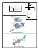
Figure 11 – Water Supply Connections
PARTS LIST
ITEM NO.
PART NO.
DESCRIPTION
NOTE: WATER FLOW
DIRECTION
BUILDING WATER
INLET
SERVICE STOP
(NOT FURNISHED)
1/4” O.D. TUBE
WATER INLET
TO COOLER
3/8” O.D. UNPLATED COP-
PER TUBE CONNECT
COLD WATER SUPPLY
DESCRIPTION
98543C
98544C
98545C
98546C
98549C
Kit - Electrical Package
Kit - EE Sensor
Kit - Solenoid Valve Replacement
Kit - Aerator Replacement
Kit - Hardware & Waterway Parts
BOTTLE FILLER REPLACEMENT
PART KITS
ITEM NO. PART NO.
27
28
29
30
31
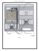
Installation Package
The components for installation are packed in
two separate boxes, regardless of the type of unit
being installed. The boxes contain the following:
Box No. 1: Wall Frame(s)
Box No. 2: Fountain(s), Arm(s) and Panels
Additional materials, as noted in the Parts List,
are also shipped in these boxes.
TROUBLESHOOTING & MAINTENANCE
Orice Assembly: Mineral deposits on orice can
cause water ow to spurt or not
regulate. Mineral deposits may
be removed from the orice by
poking with a small round le
not over 1/8” diameter, or using
a small diameter wire.
DO NOT le or cut orice
material
Stream Regulator: If orice is clean, regulate
ow as in Step 14 of the installation instructions. If
replacement is necessary, see parts list for correct
regulator part number.
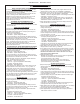
Actuation of Quick Connect Water Fittings: Cooler
is provided with lead-free connectors which utilize an
o-ring water seal. To remove tubing from the tting,
relieve water pressure, push in on the gray collar while
pulling on the tubing. (See Fig. 13) To insert tubing,
push tube straight into tting until it reaches a positive
stop (approximately 3/4”).
Note: Screw the locknut hand tight to seal
FOR PARTS, CONTACT YOUR LOCAL DISTRIBUTOR OR CALL 1.800.834.4816
REPAIR SERVICE INFORMATION TOLL FREE NUMBER 1.800.260.6640
ELKAY MANUFACTURING COMPANY • 2222 CAMDEN COURT • OAK BROOK, IL 60523 • 630.574.8484 • www.elkay.com
Figure 12 – Quick Connect FittingsFigure 11
B CA
SIMPLY PUSH IN
TUBE TO ATTACH
TUBE IS SECURED
IN POSITION
PUSH IN COLLET
TO RELEASE TUBE
OPERATION OF QUICK CONNECT FITTINGS
PUSHING TUBE IN BEFORE
PULLING IT OUT HELPS TO
RELEASE TUBE
OPERATION OF QUICK CONNECT FITTINGS
SIMPLY PUSH IN
TUBE TO ATTACH
TUBE IS SECURED
IN POSITION
PUSH IN COLLET
TO RELEASE TUBE
PUSHING TUBE IN BEFORE
PULLING IT OUT HELPS TO
RELEASE TUBE
A B C