
Installation Sheet


Page 4
EFHA14*1J
1000001998 (Rev. B - 05/16)
Fig. 6
Fig. 3
Fig. 4
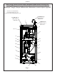
Stream height is factory set at 35 PSI. If supply pressure varies greatly from this, re-
move cover & button and adjust screw on regulator. Clockwise adjustment will raise
stream and counter-clockwise adjustment will lower stream. For best adjustment,
stream should hit basin approximately 6-1/2" (165mm) from bubbler.
La altura del chorro se determina en la fábrica a 35 PSI. Si la presión del suministro
varía demasiado de este valor, sacando cubierta y botón y ajuste el tornillo en el
regulador. El ajuste en el sentido de las agujas del reloj elevará el chorro y contra
el sentido de las agujas del reloj lo bajará. Para un mejor ajuste, el chorro deberá
pegar en el estanque a una distancia de aproximadamente 6½” (165mm) del
borboteador.
Le niveau d’écoulement est réglé en usine à 35 PSI. Si la pression varie beaucoup
de ce point, retirez couvercle et bouton et ajustez la vis de l’régleur. Si vous ajustez
dans le sens des aiguilles d’une montre, le jet augmentera et dans le sens contraire,
le jet diminuera. Le meilleur ajustement est lorsque le jet frappe le bassin à environ
6-1/2" (165mm) du barboteur.
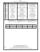
NOTE:
WHEN INSTALLING REPLACEMENT BUBBLER AND PEDESTAL, TIGHTEN
NUT ONLY TO HOLD PARTS SNUG IN POSITION.
DO NOT OVER TIGHTEN.
NOTA:
CUANDO SE INSTALE EL BORBOTEADOR DE REPUESTO Y EL PEDES-
TAL, APRIETE LA TUERCA SOLAMENTE PARA SOSTENER LAS PIEZAS
EN SU POSICIÓN.
NO APRIETE EMASIADO.
NOTE:
LORSQUE VOUS INSTALLEZ UN NOUVEAU BARBOTEUR ET SOCLE,
RESSERREZ L’ÉCROU SEULEMENT SUFFISAMMENT POUR GARDER
LES PIÈCES BIEN EN PLACE.
NE PAS TROP SERRER.
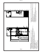
Faucet Assembly Instructions
1. Place the faucet spout through the chrome cover with the smaller diameter end
toward the faucet outlet.
2. Place the chrome collar over the faucet spout with the smaller diameter toward
the bigger diameter chrome cover in step no. 1.
3. Place the faucet spout end down inside the same diameter hole in the brass
connector.
4. Hold the chrome collar and cover up so you can get to the faucet set screw, turn
the faucet spout so it goes toward the drain on the cooler.
5. Tighten the faucet set screw gradually until faucet wil not rotate.
6. Lower the chrome collar and the chrome cover down to basin.
7. Place the chrome cover so the set screw is toward the rear of the faucet.
8. Tighten set screw until cover will not pivot.
9. Place handle on faucet with the slot toward the front of the faucet, slide the slot
into the brass pin.
10. Hold handle in snug toward faucet making sure it is seated into the brass pin,
and then tighten the handle set screw until handle will not come off the brass pin.
11. Removal of the handle is exactly opposite of the assembly process.
5
Part of
Item 22
9
Locknut
Tueraca de Fijacion
Ecrou de Blocage
Basin
Estanque
Bassin
Faucet Spout
Chrome Cover
Chrome Collar
Faucet Spout
Set Screw
Handle Set
Screw
Cover Set Screw
Cover
Cubierta
Couvercle
Button
Botón
Bouton
Regulator
Regulador
Régleur
Fig. 5
Basin
Estanque
Bassin