
Installation Sheet

97018C (Rev. C - 9/02)
EFRP8C & EFRPC8C
PAGE 3
FIG. 2
TUBE IS
SECURED
IN POSITION
SIMPLY PUSH IN
TUBE TO ATTACH
PUSH IN COLLET
TO RELEASE TUBE
PUSHING TUBE IN BEFORE
PULLING IT OUT HELPS TO
RELEASE TUBE
FIG. 3
OPERATION OF QUICK CONNECT FITTINGS
CUSPIDOR DRAIN
FOUNTAIN
DRAIN
14
12
15
19
17
25
BUBBLER ASSY
7
14
4
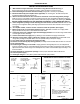
NOTE:
WHEN INSTALLING REPLACEMENT BUBBLER
AND PEDESTAL, TIGHTEN NUT (ITEM 25)
ONLY TO HOLD PARTS SNUG IN POSITION.
DO NOT OVER TIGHTEN.
11
INSTALLATION INSTRUCTIONS
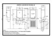
1. Wall should already be framed for the fountain using dimensions shown in Fig. 1.
Shown dimensions pertain to installation location. (Framing shown for reference only).
2. Fasten mounting box or boxes into wall cutout(s) using bolts or screws (not provided).
3. Mount fountain body (and cuspidor when applicable) on mounting box. Screws and clips are
provided for fastening fountain body to box.
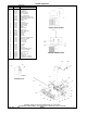
4. Remove strainer and the 3/8" O.D. tube that is inserted in it from the refrigeration package.
Install a 1/4 union (2 provided) on both the inlet and outlet line of the refrigeration package by pushing
the tubes straight into fittings until they reach a positive stop, approximately 3/4". (See Fig. 3) DO NOT
SOLDER TUBES INSERTED INTO THE STRAINER AS DAMAGE TO THE O-RINGS MAY RESULT.
5. Place refrigeration package inside mounting box and connect the chiller inlet line with the tube
coming from the regulator holder (See Page 4) and connect the chiller outlet line with line coming from
the bubbler.
6. On cuspidor models, connect 1/4 tube coiled in fountain to spreader. (See Page 4)
7. Water supply is 3/8" O.D. and waste tailpiece(s) are 1-1/4" O.D. Contractor is to supply waste
trap(s) and service stop valve in accordance with local codes.
8. Connecting lines to be unplated copper and thoroughly flushed to remove all foreign matter before
connecting to fountain assembly.
9. Connect the fountain to supply line by installing a union between the supply and fountain.
10. Electrical: Insure power supply is identical in voltage, cycle, and phase to that specified on the
refrigeration package serial plate. Never wire compressor direcly to the power supply.
11. Turn water supply on and check thoroughly for leaks.
12. Release air from tank by depressing push bar; a steady stream of water assures all air is removed.
13. Re-check for leaks.
14. Stream height is factory set at 35 PSI. If supply pressure varies greatly from this, turn adjustment
screw on regulator (item 24). Clockwise adjustment will raise the stream height and counter-clockwise
adjustment will lower stream height. For best adjustment, stream should hit basin approximately 6-1/2"
from the bubbler.
15. Rotate fan blade on refrigeration package to insure proper clearance and free fan action.
16. Connect power supply.
17. Install grill using #8 x 1.00" (25mm) PH screws and small clips provided.
8
NOTE: WATER FLOW
DIRECTION
BUILDING WATER
INLET
SERVICE STOP
(NOT FURNISHED)
1/4" O.D. TUBE
WATER INLET
TO COOLER
3/8" O.D. UNPLATED
COPPER TUBE CONNECT
COLD WATER SUPPLY