
Installation and Assembly


Page 498770C (Rev. A - 6/11)
LVRCGRN8WS*1B LVRCGRNTL8WS*1B
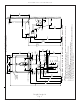
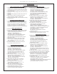
Fig. 5
Note: Screw the locknut hand tight to seal
Fig. 6
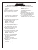
BOTTLE FILLER INSTALLATION
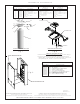
1) Remove two (2) mounting screws with 5/32” allen wrench holding top cover to Bottle Filler (See FIG. 4). Remove top cover. Note do not discard mounting
screws, they will be needed to reinstall top cover..
2) Remove wall mounting plate from Bottle Filler. Place Wall plate against wall on top of LVRC basin. Center the wall plate side to side with the LVRC basin.
Mark the six (6) mounting holes with a pencil (See FIG. 3).
3) Remove wall mounting plate from wall. NOTE: Mounting plate MUST be supported securely. Add fixture support carrier if wall will not provide adequate
support.
4) Install wall mounting plate to wall using six (6) 7/16” obround mounting holes (mounting bolts not included) (See FIG. 3). Use appropriate fasteners for
your wall type.
5)
Locate plastic bushing (provided) and place in basin hole by pushing into hole until it snaps into place. This bushing protects the water line,
and power cord from sharp edge of basin. This part must be used.
6) Place Drain Mat into position on the bottom of the Bottle Filler Unit.
7) Remove 3/8” to 1/4” reducing union from end of waterline, (do not throw away it will be needed later). Lay Bottle Filler on water cooler basin and cut
insulation from tube even with bottom of unit, remove this insulation from the 3/8” tube, but do not discard. Fish the power cord, and waterline through
the hole on top of water cooler NOTE: To prevent scratching the basin place a towel or soft cloth over the entire basin when working above it.
8) With the power cord and waterline through hole on top of water cooler place Bottle Filler on the three (3) angled tabs protruding from the wall
mounting plate, installed on wall (See Fig. 9). Make sure rubber Drain Mat is installed properly on bottom of Bottle filler (See Cover Illustration).
9) Once Bottle Filler is installed on wall plate tabs, drain mat, water line and power cord are installed properly, push top of Bottle Filler toward
wall and line up top cover two (2) holes.
10) Reinstall Top Cover on Bottle Filler (See FIG. 4) with two mounting screws from step 1 above. Caution do not over tighten screws.
11) For Single Model Installations: Install remaining tube insulation to the water line from bottle filler, connect Bottle Filler waterline inside of the water
cooler by connecting the 3/8” water line with the 3/8” to 1/4” union and short piece of poly tube that was previously installed to the tee at the evaporator
outlet.
11a) For Two Level Model Installations: Install the 1/4” poly tubing and insulation from the outlet of the filter to the union on top of the evaporator. Install
the 1/4” poly tubing and insulation from the regulator in the non-refrigerated cooler to the tee at the evaporator outlet. Install remaining tube insulation
to the water line from bottle filler, connect Bottle Filler waterline inside of the water cooler by connecting the 3/8” water line with the 3/8” to 1/4” union
and short piece of poly tube that was previously installed to the tee at the regulator inlet on the non-refrigerated cooler.
12) Install filter cartridge, remove filter from carton, remove protective cap, attach filter to filter head by firmly inserting into head and rotating filter
clockwise. NOTE: If existing plumbing rough-in locations (Drain, Water In, Electric Supply) do not allow the filter to be mounted inside the cooler cabinet
the filter can be installed horizontally below the unit. A retrofit kit is available to mount the filter beneath the cooler.
13 Turn water supply on and inspect for leaks. Fix all leaks before continuing.
14) Once unit has been inspected for leaks and any leaks found corrected plug Bottle Filler and LVRC unit into wall. Be sure to reinstall fuse to the circuit
or switch the circuit breaker back to the “ON” position.
15) Once power is applied to Bottle Filler, the GREEN LED light should illuminate showing good filter status along with the LCD Bottle Counter.
16) Verify proper dispensing by placing cup, hand, or any opaque object in front of sensor area and verify water dispenses. Note: the first initial dispenses
might have air in line which may cause a sputter. This will be eliminated once all air is purged from the line.
17) Once unit tests out, install Lower Panel back on LVRC water cooler(s). Units are now ready for use.
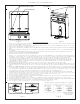
7/16” BOLT HOLES FOR
FASTENING UNIT TO WALL
UNIT CENTER LINE
TOP COVER
MOUNTING
SCREWS
Fig. 3 Fig. 4