
Specification Sheet
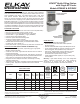

EZH2O
®
Bottle Filling Station
with Single EZ Cooler
Models EZS8WS & EZSDWS
2222 Camden Court
Oak Brook, IL 60523
elkay.com
Printed in U.S.A.
© 2015 Elkay
RATED FOR INDOOR USE ONLY
REDUCE HEIGHT BY 3 INCHES FOR INSTALLATION OF CHILDRENS ADA COOLER
Job Name: ____________________________________
Model: _______________________ Qty. ____________
Contact: ______________________________________
Approval Signature: _____________________________
Notes:
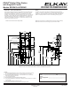
LEGEND:
A = Recommended Water Supply location. Shut-off Valve (not furnished) to accept
3/8” O.D. unplated copper tube. Up to 3” (76mm) maximum out from wall.
B = Recommended Waste Outlet location. To accommodate 1-1/4” nominal drain.
Drain stub 2” (51mm) out from wall.
C = 1-1/4” Trap (not furnished).
D = Electrical Supply (3) Wire Recessed Box Duplex Outlet.
E = Insure proper ventilation by maintaining 6” (152mm) minimum clearance from cabinet
louvers to wall.
F = 7/16” (11mm) Bolt Holes for fastening to wall.
**New Installations Must Use Ground Fault Circuit Interrupter (GFCI).
NOTICE
This water cooler must be connected to the water supply using a dielectric
coupling. The cooler is furnished with a non- metallic strainer which meets this
requirement. The drain trap which is provided by the installer should also be
plastic to completely isolate the cooler from the building plumbing system.
IMPORTANT! INSTALLER PLEASE NOTE:
These units are designed and built to provide water to the user which has not
been altered by materials in the cooler waterway. The grounding of electrical
equipment such as telephone, computers, etc. to water lines is a common
procedure. This grounding may be in the building but may also occur away from
the building. This grounding can cause electrical feedback into a water cooler
creating an electrolysis which results in a metallic taste or an increase in the
metal content of the water. This condition is avoidable by installing the cooler
using the proper materials as shown.
Bottle Filler unit will mount on bracket attached to wall by 6 holes (as shown).
Water and electrical will connect through pre-punched hole in basin.
Model shown with Flexi-Guard
®
Safety Bubbler.
F
E
A
B
7/16" X 3/4" OBROUND
(11mm X 19mm) HOLES (6)
C
D
E
9/32" O HOLES
(7mm) (12)
FINISHED FLOOR
L
C
7"
178mm
7"
178mm
17 7/8"
454mm
6 3/8"
162mm
6 3/8"
162mm
2"
51mm
2"
51mm
5 3/4"
146mm
13 15/16"
354mm
17 7/16"
443mm
19"
483mm
28 13/16"
732mm
51 9/16"
1310mm
18 7/8"
479mm
12 1/2"
318mm
31 5/16"
796mm
RIM
HEIGHT
32 7/8"
835mm
ORIFICE
HEIGHT
21 7/8"
556mm
2"
51mm
3 7/8"
98mm
7"
178mm
7"
178mm
28 13/16"
732mm
2"
51mm
2 7/8"
73mm
15"
381mm
27"
686mm
ADA
REQUIREMENT
8 1/16"
205mm
19"
483mm
3 9/16"
90mm
5 7/8"
150mm
3"
77mm
2"
51mm
38 1/2"
979mm
ACTIVATION
SENSOR
HANGER BRACKET
ROUGH-IN DIMENSIONS