
Instructions / Assembly


0000001029 (Rev. G - 04/18)
EDFPBM117WS EDFPBM117WS-F
Page 4
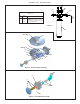
NOTE:
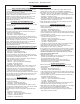
When installing replacement bubbler and pedestal, tighten
locknut only to hold parts snug in position. Do Not overtighten.
Figure 6 - Bubbler Details
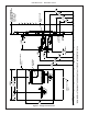
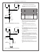
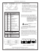
Figure 4 - Upper Panel Installation
Figure 5 - Fountain Installation
15 Reset Switch
22
27, 28, 29, 30, 31
19
23
23
View From Rear
5
Basin
1
Locknut
22
17
8. Install fountains with (8) 5/16-18 HHMS & (8) 5/16-18 nuts
(provided) (Fig. 5). Connect the ¼” water lines from each
fountain to the remaining openings on the tee at the remote
chiller (cut lines to t as needed).
9. Attach waste tubes (1-1/4” O.D.) to 1-1/4” O.D. slip trap.
Trap on the bottle ller side must be 1-1/2” O.D. (provided by
others).
10. Make nal water supply connections.
11. These products are designed to operate on 20-105 PSI
supply line pressure. If inlet pressure is above 105 PSI, a
pressure regulator must be installed in the supply line.
Caution: Any damage caused by connecting these products
to a supply line with pressure lower than 20 PSI or higher
than 105 PSI IS NOT covered under warranty.
12. Make electrical connections to the bottle ller and remote
chiller. The LCD Bottle counter should illuminate.
13. Verify proper dispensing from the bottle ller by placing a cup,
hand or any opaque object in front of sensor area and verify
water dispenses. Note: the rst initial dispenses might have air
in the line which may cause a sputter. This will be eliminated
once all air is purged from the line. A steady stream of water
assures all air is removed. The sensor has a 20 second maxi
mum ON time. It may be necessary to step away from the
beam a few times to purge all air. Check for leaks.
14. Check stream height from bubbler. Stream height is factory set
for 35 PSI supply. If supply pressure varies greatly from this,
remove push button (Item 7 - Fig. 9) and adjust the screw
on the regulator (Item 8 - Fig. 9). To remove push button,
remove setscrew from bottom of sleeve (Item 6). Insert a small
punch in screw hole and push up while grasping the push but
ton and pull forward removing the push button. Clockwise
adjustment will raise stream height and counterclockwise
movement will lower stream height. For best adjustment
stream should hit basin approximately 6-1/2” from the bubbler.
Reassemble the push button by pushing in on button until the
push button catches in the sleeve. Reinstall the setscrew (Item
24) in the sleeve (Item 6).
15. Install the cover plates.
16. Install the bottom panel, tighten screws (Fig. 4).
17. Optional: Mount optional panels. Slide tongue of panel under
edge of already installed panel. Tighten screws.
Back
Panel
16
16