
Installation Sheet


ERPBD8WSC LRPBD8WSC
1000002504 (Rev. F - 03/19)
Page 3
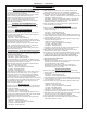
Figure 3 - LZWS-LRPB Tube Routing
1. Make water supply connections. Install a shut-off valve
and union connection to building water supply (valve and
union not provided). Turn on water supply and ush the
line thoroughly.
Caution: DO NOT SOLDER tubes inserted into the
strainer or lter head as damage to the o-rings may result.
2. Install mounting frame (instructions supplied with mounting
frame.
3. (For EZWS-ERPBM8K) Install the strainer on the inlet tube of
the chiller. Install 1/4” x 1/4” x 3/8” tee on outlet tube of the chiller
per (Fig. 2).
4. (For LZWS-LRPBM8K) Install the lter head to the bracket
then install bracket to side of chiller (Fig. 9). Next install lter to
lter head and plumb from lter outlet to the chiller inlet with 1/4”
poly tubing and 1/4” x 1/4” union per (Fig. 3).
4a. Install chiller on shelf, install 1/4” X 1/4” x 3/8” Tee on chiller
outlet tube. With the back panel standing close to the frame,
connect the 3/8” poly tube coming from the bottle ller to the tee
(Fig. 3).
Note: Building construction must allow for adequate air ow
on both sides, top & back of chiller. A minimum of 4” (102 mm)
on both sides & top is required. See chiller installation for ad-
ditional instructions.
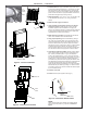
5. Hang main panel on mounting frame hanger. Plug bottle ller into
wall box receptacle. Make sure the power cord, reset switch wire
& poly tube do not get pinched between the panel & mounting
frame. Ensure the panel engages at the top. Align fountain holes
with mounting frame holes.
6. Remove protective coating from main panel.
7. Install reset switch for bottle ller (Fig. 4A). Snap the switch
into position after locating wires through slot. Wrap up the
excess cord.
Figure 2 - EZWS-ERPB Tube Routing
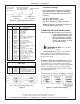
REQUIRED TOOLS AND MATERIALS
These tables show special tools and/or additional materials
(not provided) which are necessary to complete installation
of these units:
Special Tools
Item
Description
Quantity
NONE
Additional Materials Not Included
Item
Description
Quantity
Unplated copper inlet pipe
Service Stop/Shut-off Valve
90° 1-1/4” Drain Line
1-1/4” Tee Drain Line
1
2
3
4
1
1
1
1
TO BUBBLER
12
25
12
CHILLER
OUTLET
WATER
INLET
15
30
TO BOTTLE
FILLER
CHILLER
INLET
12
14
TO BUBBLER
15
TO BOTTLE
FILLER
30