
Installation Sheet


Elkay Manufacturing Company 8
Built-in Filtered Water Dispenser
(630) 574-8484
1000005232 (
Rev. B - 05/19)
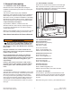
A 1/4 inch offset helps conceal any irregularities at the top of the wall
opening.
3. Using a bubble level, level the water dispenser and
attach it to the wall studs using four #8 athead
screws.
4. Locate the electrical gang box, at the lower right-hand
corner of the water dispenser, and remove the cover.
CAUTION
Follow all safety
practices and industry
regulations and standards when connecting any
electrical device.
5. Connect a 110 VAC power supply to the water
dispenser. Route the wiring through the wall into the
bottom of the electrical gang box.
• A 15 AMP GFCI Circuit Breaker is required for safe
installation.
• Route the appropriate electrical wiring through a
wiring clamp into the gang box.
• Tighten the wiring clamp to prevent the wire from
being pulled out of the gang box.
• Connect black wire to supplied voltage line (black)
wire and the white wire to neutral.
• Use provided wire nuts to insulate the connections.
• If required by code a green grounding screw can be
used to connect a grounding wire inside the gang
box.
NOTICE
Do not use a cord with a three-
prong plug to power this unit.
Note: If an optional filter unit will be installed under the
water dispenser, the space behind that filter box is
limited so make sure any electrical wiring will not
interfere with mounting the filter box into the wall.
Refer to "4.3 Critical Depth Dimensions" on page
6 for additional information.
4.5.2 Installing the Filter Box
1. If the lter unit is being installed in the wall opening
under the water dispenser, replace the front cover of
the water dispenser to help locate and align the lter
box under the water dispenser.