
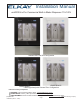
Instructions / Assembly


Elkay Manufacturing Company (630) 574-8484
1000005449 (Rev. E - 04/23)
Page 8
4. Installation
4.1 Tools Required
Tool Used For
Tape Measure Locating mounting opening
Wall Cutting Toll Remove section of wall to insert unit
Level Proper mounting into the wall cavity
Phillips Screw Driver Remove electrical box cover
Various Electrician's
Hand Tools
Connecting power source to the unit's
wiring
Various Plumber's
Hand Tools
Connecting unit's plumbing to the
household water source and waste drain
3/32 Allen Wrench Remove the front covers
4.2 Installer Supplied Parts Required
Description Qty.
#8 Flathead Screws 1-1/4" long 8
Electrical
12/2 with ground electrical wire (depending on local
building codes the installation could require rigid conduit,
armored cable, or plastic sheath NM-B cable)
—
Electrical wire nuts (appropriate size) —
GFCI circuit (connected into an electrical circuit) 1
Water
3/8" flexible water tubing (copper or plastic)(insulated) —
Quarter-turn shut off valve at the location of the water
source
1
1/4 inch copper or plastic tubing if a remote filter is installed
(insulated)
15 feet
or less
Optional Catch Basin Drain
1-1/4" P-trap and related parts —
Plumbers Putty —
Additional 3/4 inch drain hose if the installation requires a
longer drain hose than the supplied 13 inch long hose
All-pole Switch (A disconnection incorporated in the fixed
wiring shall be provided, including an all-pole switch with
appropriate rating voltage and current connecting with
supply mains and the product)
1
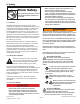
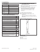
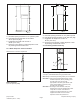
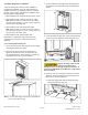
4.3 Critical Depth Check and Cutting Size
Mounting Dimensions
1. Make sure the wall cavity is deep enough to house the
water dispenser (dimension A).
2. If the optional lter box unit will be installed, make
sure there is adequate space to route electrical
wiring between the wall and the lter box which
is approximately 1-5/8" for standard 2 x 4 wall
construction.
4.3.1 Water Dispenser with Filter Box
Note: For water dispenser without filter box, see
section 4.3.2.
A filter box should not be installed in conjunction
with a chiller. If planning to install with a chiller, see
section 4.3.2.
Dimension A is a minimum depth requirement.
A
B
Water Dispenser
A) 3-7/8" (97 mm) deep.
Filter Unit
B) 2-3/8" (61 mm) deep.