
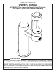
Installation Sheet


PAGE 5
4410BFFR_FTN LK 4410BFFR_FTN
98878C (Rev. B - 12/15)
28955C*
45931C
66816C
98532C
98677C
98679C
98680C
98681C
98683C
98685C
98686C
98836C
98901C
98902C
P05031
45832C*
45833C*
66346C
55960C
66461C
720001843
75521C
75565C
56123C
56307C
1
2
3
4
5
6
7
8
9
10
11
12
13
14
15
16
17
18
19
20
21
NS
NS
NS
NS
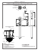
Cover - Round Plate
Outdoor Bottle Filler Drain Plug
Tube - Drain (Arm Only)
Kit - "O" Rings and Fittings
Kit - Gasket
Kit - Nozzle
Kit - Aerator
Kit - Bottle Filler Trim
Kit - Plastic Drain
Kit - 4400 Series Hardware
Kit - Bottle Filler Waterway
Single Control Valve System
Kit - Frz Resist Push Button
Single Control Valve Assy. (BF)
Aerator
Panel - Access
Cover - Panel
Tube - Drain
Fitting 1-1/4" to 3/4" Pressure
Fitting - 1-1/4" x 1-1/4" Rubber
Fitting - Slip Ell Drain
Bit - Pinned Torx T-27
Fitting - Double Male Connector
Tubing - 1/8" Poly (Cut To Length) - To Actuator
Tubing - 3/8" Poly (Cut to Length)
ITEM NO. PART NO.
PARTS LIST
DESCRIPTION
The following items are included with
the 4410BFFR Fountain
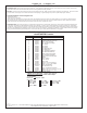
TROUBLE SHOOTING
Insufcient Flow: Check that the shut-off valve is wide open. Verify minimum 20 PSI supply pressure. Clean inlet strainer screen located in the valve body.
Clean rubber orice in ow control located below frost line in bushing between barb tting and valve.
No Flow: Check for leaks in the air tubing going from the push button to the valve. Make sure the air tubing compression nut is hand tight. Disconnect air tube
from push button. Place nger over air outlet. Push button to test diaphragm. Tighten diaphragm cap screws. Replace diaphragm if necessary.
Continued Insufcient or Varied Height of Flow:
• Replace ow control.
• Check for kinks in the tubing.
• Remove the PVC cap from the PVC column. Remove the valve assembly from the PVC column by carefully pulling up on the nylon strap. Pressure test the
valve assembly for leaks. Replace the valve into the PVC column. Make sure the supply hose coils into the bottom of the PVC column without any kinks and
double check that the valve is positioned fully at the bottom of the PVC column. Cap the PVC column.
Continuous Flow: Insure that push button is not obstructed and springs back to normal position. Remove four screws which secure plastic diaphragm block
to valve body. Pull plastic and rubber diaphragm assembly out of valve body. Locate tiny hole in rubber diaphragm just under lip of plastic part. Clean debris
from this hole. Inspect valve seat for grooves. If valve seat was OK and diaphragm hole was free from debris, inspect rubber button located at center of oating
steel disc in valve diaphragm block assembly. If button is worn, turn disc over or replace it. If diaphragm and seats are in good condition, stretch spring slightly.
Spring is located behind oating stainless steel plate. Insure that air bleed port on valve plastic block assembly is not plugged.
PRINTED IN U.S.A.
Halsey Taylor – halseytaylor.com
Elkay – elkay.com
FOR PARTS CONTACT YOUR LOCAL DISTRIBUTOR OR CALL TECHNICAL SERVICES AT 1.800.834.4816
2222 CAMDEN COURT, OAK BROOK, ILLINOIS 60523
*select color option to complete part number
*FINISH COLOR OPTIONS – Choose color option to
complete your model number, add as sufx example:
4410BFFRKEVG
Matte nish: Evergreen = EVG
Gloss nish:
Beige = BGE Gray = GRY Terracotta = TER
Black = BLK Orange = ORN White = WHT
Blue = BLU Purple = PUR Yellow = YLW
Brown = BRN Red = RED