
Specification Sheet

(79mm)
1
(29mm)
(206mm)
(238mm)
(476mm)
MINIMUMDEPTH
(16mm)(467mm)
(41mm)
(41mm)
2
(730mm)
(927mm)
8
(203mm)
(114mm)
(29mm)
(279mm)
FINISHED FLOOR
(
A
REQUIREMENT
(863mm)
(1059mm)
BACK WALL LINE
(519mm)
(517mm)
(73mm)(73mm)(356mm)(356mm)
(978mm)
4
(121mm)
SHUTOFFVALVE BY OTHERS
COLD WATER OUTLET
ELECTRICAL INLET
1
FURNISHED
5
(140mm)
(89mm)
(25mm)
(79mm)
1
(29mm)
(206mm)
(238mm)
(476mm)
12" MINIMUM DEPTH
(16mm)
(467mm)
(41mm)
(41mm)
2
(730mm)
(927mm)
8
(203mm)
(114mm)
(29mm)
(279mm)
FINISHED FLOOR
(
A
REQUIREMENT
(863mm)
(1059mm)
BACK WALL LINE
(519mm)
(517mm)
(73mm)(73mm) (356mm)(356mm)
(978mm)
4
(121mm)
SHUT OFF VALVE BY OTHERS
COLD WATER OUTLET
ELECTRICAL INLET
1
FURNISHED
5
(140mm)
(89mm)
(25mm)
(12 REQ’D-NOT PROVIDED)
(959mm)
(114mm)
(29mm)
LOCA
TION ON CHILLER
TO FLOOR LINE
(203mm)
MIN DEPTH
(130mm)
FLOOR LINE
(953mm)
CHILLER SHELF
(4 REQ’D-NOT PROVIDED)
HOOK RODS (2)
(NOT PROVIDED)
(NOT PROVIDED)
FRAME
SHOWN (NOT PROVIDED)
(12 REQ’D-NOT PROVIDED)
(959mm)
(114mm)
(29mm)
LOCATION ON CHILLER
TO FLOOR LINE
(203mm)
MIN DEPTH
(130mm)
FLOOR LINE
(953mm)
CHILLER SHELF
(4 REQ’D-NOT PROVIDED)
HOOK RODS (2)
(NOT PROVIDED)
(NOT PROVIDED)
FRAME
SHOWN (NOT PROVIDED)
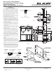
LRPBM28RAK MOUNTING FRAME INSTRUCTIONS
1.Cut a square rectangular wall opening 37-1/2"
(953mm) W x 37-3/4" (959mm) H and 4-1/2"
(114mm) above the floor line. These dimensions
are required to obtain proper rim and bubbler
heights for compliance with ANSI standard
A117.1. (See Figure 2)
2.Reinforce the wall opening on all sides so that it
will adequately support the water fountain. This
reinforcement must supp
ort up to 150 lbs static
loa
d and provide a means for securing the frame
assembly in place.
NOTE: Building construction must allow for
adequate air flow on both sides and top of remote
chiller unit. Minimum of 4" (102mm) is required.
(See Figures 1 & 2)
3.Install plumbing and electrical rough-ins. See
Figure 1 for location of the supply water inlet to
chiller and for the location of the waste water
outlet. A
junction box for a (3) wire, 10 amp branch
cir
cuit is provided on the inside of the chiller.
(Standard 120 Volts, 60 Hz and single phase)
See Figure 2 for the electrical inlet location.
4.Remove frame assembly and related hardware
from packaging. Attach the two frames together
thru the upright supports with (4) 5/16" x 3/4"
(19mm) long bolts and nuts (not provided).
Tighten securely.
NOTE: Frame with high
er upper channel to be on
right
side.
5.Install the frame assembly squarely in wall
opening with frame upright support edges flush
with the finished wall face. Secure the frame to the
wall thru holes with (12) 5/16" x 2" (51mm) long
lag bolts or screws (not provided). Tighten securely.
NOTE: Be sure that frame is squared in location.
Do not use less than required screw quantity and
size.
6.Attach the chiller
shelf support rods to
the right
side frame uprights at the second set of holes
counting from the bottom and to the shelf at the
(2) side holes. Line up the other shelf holes with
the frame bottom holes and fasten the assembly
to the wall using appropriately sized wood screws
or bolts and nuts (not provided). (See Figure 2)
FIG.1
FIG. 2
IMPORTANT!
INSTALLER PLEASE NOTE:
The grounding of electrical equipment
such as tele-
pho
ne, computers, etc., to water lines is a common
procedure. This grounding may be in the building or
may occur away from the building. This grounding
can cause electrical feedback into a water cooler,
creating an electrolysis which causes a metallic
taste or causes an increase in the metal content of
the water. This condition is avoidable by using the
proper materials as indicated below.
The drain fittings which are provided by the installer
sh
ould also be plastic to electrically isolate the cooler
from the building plumbing system.
NOTE:WATERFLOW
DIRECTION
SERVICE STOP
(NOTFURNISHED)
3/8"O.D.TUBECONNECT
COLD WATERSUPPLY
1/4"O.D.TUBE
WATERINLET
TOCOOLER
BUILDINGWATER
INLET
NOTE: WATERFLOW
DIRECTION
SERVICE STOP
(NOT FURNISHED)
3/8" O.D. TUBE CONNECT
COLD WATER SUPPLY
1/4" O.D. TUBE
WATER INLET
TO COOLER
BUILDING WATER
INLET
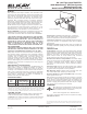
OPERATIONOFQUICKCONNECTFITTINGS
SIMPLYPUSH IN
TUBETOATTACH
TUBEIS SECURED
IN POSITION
PUSH IN COLLET
TORELEASETUBE
PUSHINGTUBEIN BEFORE
PULLINGITOUTHELPSTO
RELEASETUBE
BA
C
OPERATION OF QUICK CONNECT FITTINGS
SIMPLY PUSH IN
TUBE TO ATTACH
TUBE IS SECURED
IN POSITION
PUSH IN COLLET
TO RELEASE TUBE
PUSHING TUBE IN BEFORE
PULLING IT OUT HELPS TO
RELEASE TUBE
BA
C
Elkay
2222 Camden Court
Oak Brook, IL 60523
elkay.com
Printed in U.S.A.
©2015 Elkay
12-43D (Rev. 12
/15)
No Lead Two-Level SwirlFlo
®
with WaterSentry
®
VII Filter System
Barrier-Free Access
Model LRPB(M)28RAK (Reversed)
®
®
ROUGH-IN DIMENSIONS
WaterSentry
®
VIIFilterSystem
WaterSentry
®
VII Filter System