
Specification Sheet

G re e nS pe c
®
L is ted Tw o-L e ve l S wirlflo
®
With Water S e ntry
®
VII F ilte r S ys tem
B ar r ie r- F re e A c c es s
M ode ls LRPBGRNM(V)28K
®
®
R O U G H - I N D I M E N S I O N S
E lkay
2222 C amden C ourt
Oak B rook, IL 60523
elkay.com
Printed in U.S .A.
© 2015 Elkay
12-66A (R ev. 1/15
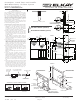
LR PB GR NM28K MOUNTING FR AME INS TR UC TIONS
1. C ut a squa re rec tangular wall opening 37-1/2"
(476mm) W x 37-3/4" (959mm) H and 4-1/2"
(114mm) above the floor line. These dimensions
are required to obtain proper rim and bubbler
heights for compliance with ANS I s tandard.
2. R einforc e the wall opening on all s ides s o that i
t
will adequately s upport the water fountain. This
reinforcement must support up to 150 lbs static
load and provide a means for securing the frame
ass embly in place.
NOT E : B uilding cons truc tion mus t allow for
adequate air flow on both s ides and top of remote
chiller unit. Minimum of 4" (102mm) is required.
(S ee Figures 1 & 2)
3. Ins tall plumbing and elec tric al rough-ins . S ee
Figure 1 for location of the suppl
y water inlet to
chiller and for the location of the waste water
outlet. A junction box for a (3) wire, 10 amp branc h
circuit is provided on the inside of the chiller.
(S tandard 120 Volts, 60 Hz and single phas e)
S ee Figure 2 for the electrical inlet location.
4. R emove frame as sembly and rela ted hardware
from packaging. Attach the two frames together
thru the upright s upports with (4) 5/16" x 3/4"
(19mm) l
ong bolts and nuts (not provided).
Tighten securely.
NOT E : Frame with higher upper channel to be on
left side.
5. Ins tall the frame a s s embly squarely in wall
opening with frame upright support edges flush
with the finished wall face. S ecure the frame to the
wall thru holes with (12) 5/16" x 2" (51mm) long
lag bolts or screws (not provided). Tighten securely.
NOT E : B e s ure that frame is squared in location.
Do
not us e les s than required s crew quantity and
size.
6. Attac h the c hiller s helf s upport rods to the right
side frame uprights at the second s et of holes
counting from the bottom and to the s helf at the
(2) side holes . Line up the other shelf holes with
the frame bottom holes and fasten the assembly
to the wall using appropriately s ized wood s crews
or bolts and nuts (not provided). (S ee Figure 2)
IM P OR TANT !
I
NS TA L L E R P L E A S E N O T E :
The grounding of electrical equipment s uch as tele-
phone, computers, etc., to water lines is a common
procedure. This grounding may be in the building or
may occur away from the building. This grounding
can cause electrical feedback into a water cooler,
creating an electrolysis which causes a metallic
taste or causes an increas e in the metal content of
the water. This condition is a
voidable by using the
proper materials as indicated below.
The drain fittings which are provided by the installer
should also be plastic to electrically isolate the cooler
from the building plumbing system.
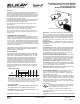
NOTE: WATERFLOW
DIRECTION
SERVICE STOP
(NOT FURNISHED)
3/8" O.D. TUBE CONNECT
COLD WATER SUPPLY
1/4" O.D. TUBE
WATER INLET
TO COOLER
BUILDING WATER
INLET
NOTE: W ATE R FLOW
DIRECTION
SERVICE STOP
(NOT FURNISHED)
3/8" O.D. TUBE CONNECT
COLD W ATER S UPP LY
1/4" O.D. TUBE
WATE R INL E T
TO COOLER
BUILDING W ATE R
INLET
OP ER ATION OF QUIC K C ONNECT FITTINGS
SIMPLY PUSH IN
TUBE TO A T TACH
TUBE IS SECURED
IN POSITION
PUSH IN COLLET
TO RELEASE TUBE
PUSHING TUBE IN BEFORE
PULLING IT OUT HELPS TO
RELEASE TUBE
BA
C
5/16" SCREWS OR BOLTS
(12 REQ'D - NOT PRO
VIDED)
37-3/4"
(959mm)
4-1/2"
(114mm)
1-1/8"
(29mm)
ELECTRI
CAL INLET
LOCATION
ON CHILLER
TO FLOO
R LINE
8"
(203mm)
BACK OF
WALL
TO BE 12
"
(305mm)
MIN. DEP
TH
5-1/8"
(130mm)
FLOOR LINE
37-1/2"
(953mm)
CHILLER SHELF
BOLT FRAMES T
OGETHER
WITH 5/16" X 3/4" (1
9mm) BOLTS
(4 REQ'D - NOT PR
OVIDED)
HOOK RODS (2)
SCREWS OR BOLTS
(NOT PROVIDED
5/16" HEX NUT
(4 REQ'D)
(NOT PROVIDED)
FRAME
WOOD OR
STEEL FRAME
SHOWN (N
OT PROVIDED)
FIG. 1
FIG. 2
3-1/8"
(79mm)
1-1/8"
(29mm)
8-1/8"
(206mm)
9-3/8"
(238mm)
18-3/4"
(476mm)
12"
(305mm)
MINIMUM DEPTH
5/8"
(16mm)
18-3/8"
(467mm)
1-5/8"
(41mm)
1-5/8"
(41mm)
28-3/4"
(730mm)
36-1/2"
(927mm)
8"
(203mm)
4-1/2"
(114mm)
1-1/8"
(29mm)
11"
(279mm)
FINISHED FLOOR
27"
(686mm)
ADA
REQUIREMENT
33-15/16"
(863mm)
41-11/16"
(1059mm)
BACK WALL LINE
20-7/16"
(519mm)
20-3/8"
(517mm)
2-7/8"
(73mm)
3/8" O.D. COPPER TUBE
WATER INLET ON CHILLER
SHUT OFF VALVE BY OTHERS
3/8" O.D. COPPER TUBE
COLD WATER OUTLET
ELECTRICAL INLET
1-1/4" (32mm)
WASTE TUBES
FURNISHED
2-7/8"
(73mm)
14"
(356mm)
14"
(356mm)
38-1/2"
(978mm)
4-3/8"
(121mm)
5-1/2"
(140mm)
WaterSentry
®
VII Filter System
5/16" SCREWS OR BOLTS
(12 REQ'D - NOT PROVIDED)
37-3/4"
(959mm)
4-1/2"
(114mm)
1-1/8"
(29mm)
ELECTRICAL INLET
LOCATION ON CHILLER
TO FLOOR LINE
8"
(203mm)
BACK OF WALL
TO BE 12"
(305mm)
MIN. DEPTH
5-1/8"
(130mm)
FLOOR LINE
37-1/2"
(953mm)
CHILLER SHELF
BOLT FRAMES TOGETHER
WITH 5/16" X 3/4" (19mm) BOLTS
(4 REQ'D - NOT PROVIDED)
HOOK RODS (2)
SCREWS OR BOLTS
(NOT PROVIDED
5/16" HEX NUT
(4 REQ'D)
(NOT PROVIDED)
FRAME
WOOD OR STEEL FRAME
SHOWN (NOT PROVIDED)
FIG. 1
FIG. 2
3-1/8"
(79mm)
1-1/8"
(29mm)
8-1/8"
(206mm)
9-3/8"
(238mm)
18-3/4"
(476mm)
12"
(305mm)
MINIMUM DEPTH
5/8"
(16mm)
18-3/8"
(467mm)
1-5/8"
(41mm)
1-5/8"
(41mm)
28-3/4"
(730mm)
36-1/2"
(927mm)
8"
(203mm)
4-1/2"
(114mm)
1-1/8"
(29mm)
11"
(279mm)
FINISHED FLOOR
27"
(686mm)
ADA
REQUIREMENT
33-15/16"
(863mm)
41-11/16"
(1059mm)
BACK WALL LINE
20-7/16"
(519mm)
20-3/8"
(517mm)
2-7/8"
(73mm)
3/8" O.D. COPPER TUBE
WATER INLET ON CHILLER
SHUT OFF VALVE BY OTHERS
3/8" O.D. COPPER TUBE
COLD WATER OUTLET
ELECTRICAL INLET
1-1/4" (32mm)
WASTE TUBES
FURNISHED
2-7/8"
(73mm)
14"
(356mm)
14"
(356mm)
38-1/2"
(978mm)
4-3/8"
(121mm)
5-1/2"
(140mm)
Wate rS entry
®
VII Filter S ystem
Flexi-Guard
®
Bubbler (standard)
Vandal-Resistant Bubbler (optional)