LVRCDWS*A, *2A LVRCTLDDWSC*A, *2A LVRC8WS*1A, *2A, *3A LVRCTL8WSC*1A, *2A, *3A INSTALLATION, CARE & USE MANUAL LVRC8WS, LVRC8WSJO, LVRCTL8WS, LVRCTL8WSJO, Factory Prep EZH2O Bottle Filling Station and Cooler IMPORTANT THIS IS AN INDOOR APPLICATION ONLY. ALL SERVICE TO BE PERFORMED BY AN AUTHORIZED SERVICE PERSON. Model LVRC8WS Model LVRCTL8WS Page 1 98980C (Rev.
LVRCDWS*A, *2A LVRCTLDDWSC*A, *2A LVRC8WS*1A, *2A, *3A LVRCTL8WSC*1A, *2A, *3A TOOLS REQUIRED BUT NOT PROVIDED: SAFETY GLASSES GLOVES ELECTRIC DRILL 3/4” WRENCH OR CRECENT WRENCH UTILITY KNIFE TAPE MEASURE PENCIL CENTER PUNCH 1/2” SOCKET & RATCHET WRENCH 5/32” ALLEN WRENCH IMPORTANT! INSTALLER PLEASE NOTE. THE GROUNDING OF ELECTRICAL EQUIPMENT SUCH AS TELEPHONE, COMPUTERS, ETC. TO WATER LINES IS A COMMON PROCEDURE. THIS GROUNDING MAY BE IN THE BUILDING OR MAY OCCUR AWAY FROM THE BUILDING.
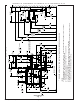
Page 3 A D B 5" 127mm 1-1/4" 32mm 7" 178mm 2-1/2" 63mm 11/16" 18mm FINISHED FLOOR 4-1/2" 114mm 10" 254mm 2-7/16" 63mm 3-1/2" 89mm 1-1/4" 32mm 7" 178mm 2-9/16" 65mm 7-1/4" 185mm 13-7/8" 352mm F E 4-9/16" 116mm 18-1/2" 470mm * 27" 686mm 31-15/16" 811mm RIM HEIGHT 33-1/16" 840mm ORIFICE HEIGHT 48" 1219mm 51-1/8" 1298mm LVRC8WS 8" 203mm 12-5/16" 312mm C 2-5/8" 66mm HANGER BRACKET 18-9/16" 472mm 6-1/4" 159mm 5-1/8" 131mm 6-3/4" 171mm 1-1/2" 38mm LEGEND: A = RECOMMENDED WATER
98980C (Rev. G- 01/15) Single Rough-In Fig. 1 Page 4 20-3/8" 518mm 37-1/2" 952mm 5" 127mm 2-9/16" 65mm F 7-1/4" 185mm E 6-1/2" 165mm O 5/16" 8mm HOLES (5 PL) 1-3/8" 35mm C L B FINISHED FLOOR 10" 254mm 2-7/16" 63mm 11/16" 18mm CL 6-1/4" 159mm 1-1/4" 32mm 7" 178mm 3-1/2" 89mm 4-1/2" 114mm D 18-1/2" 470mm 16-5/16" 414mm 18-3/4" 476mm 20-1/8" 511mm 25-1/8" 638mm 27" 686mm LEGEND: A = RECOMMENDED WATER SUPPLY LOCATION 3/8” O.D.
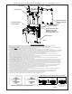
LVRCDWS*A, *2A LVRCTLDDWSC*A, *2A LVRC8WS*1A, *2A, *3A LVRCTL8WSC*1A, *2A, *3A MOUNTING SCREWS TOP COVER BOTTLE FILLER MOUNTING BRACKET FOR FASTENING UNIT TO WALL MOUNTING SCREWS DO NOT REMOVE MOUNTING SCREWS DO NOT REMOVE NOTE: TRIM PLATES MUST BE INSTALLED ON THE INSIDE OF THE BOTTLE FILLER SIDE PANEL SLOTS. WATER COOLER Fig. 3 BOTTLE FILLER INSTALLATION 1) Remove wall mounting plate(s) from Cooler(s). Install Wall Mounting Plate(s) as per rough-in diagrams on sheet 2 or 3 of this instruction.
LVRCDWS*A, *2A LVRCTLDDWSC*A, *2A LVRC8WS*1A, *2A, *3A LVRCTL8WSC*1A, *2A, *3A REMOVAL OF BOTTLE FILLER FOR SERVICING 1) Turn off the water supply to the Water Cooler(s). Unplug and/or turn off Circuit Breaker to Cooler(s) and Bottle Filler. NOTE: the Lower Front Panel of the cooler(s) may need to be removed. To prevent scratching the basin place a towel or soft cloth over the entire basin when working above it.
LVRCDWS*A, *2A LVRCTLDDWSC*A, *2A LVRC8WS*1A, *2A, *3A LVRCTL8WSC*1A, *2A, *3A BF9 PROGRAM SETTING THE CONTROL BOARD VERIFY CONTROL BOARD SOFTWARE 1) To verify the software program of the control board the unit will need to be shut down and restarted. The chiller (if present) does not need to be shut down and restarted. 2) The units lower panel must be open to access the power cord and wall outlet. 3) Shut down the unit by unplugging the power cord from the wall outlet.
LVRCDWS*A, *2A LVRCTLDDWSC*A, *2A LVRC8WS*1A, *2A, *3A LVRCTL8WSC*1A, *2A, *3A BF11 PROGRAM SETTING THE CONTROL BOARD VERIFY CONTROL BOARD SOFTWARE 1) To verify the software program of the control board the unit will need to be shut down and restarted. The chiller (if present) does not need to be shut down and restarted. 2) The units lower panel must be open to access the power cord and wall outlet. 3) Shut down the unit by unplugging the power cord from the wall outlet.
LVRCDWS*A, *2A LVRCTLDDWSC*A, *2A LVRC8WS*1A, *2A, *3A LVRCTL8WSC*1A, *2A, *3A REPLACEMENT PART KITS PART NO.