
Installation Sheet


Page 5 98980C (Rev. G - 01/15)
LVRCDWS*A, *2A LVRCTLDDWSC*A, *2A LVRC8WS*1A, *2A, *3A LVRCTL8WSC*1A, *2A, *3A
Fig. 4
Note: Screw the locknut hand tight to seal
Fig. 5
BOTTLE FILLER INSTALLATION
1) Remove wall mounting plate(s) from Cooler(s). Install Wall Mounting Plate(s) as per rough-in diagrams on sheet 2 or 3 of this instruction.
NOTE: Mounting plate(s) MUST be supported securely. Add xture support carrier if wall will not provide adequate support.
2) For Single Model Installations: Install water cooler onto wall bracket and secure to wall. Connect drain and water inlet to cooler as required (See rough-
in on page 2). DO NOT connect power to cooler at this time or turn water supply on.
2a) For Two Level Model Installations: Install lower water cooler only at this time onto bracket as per rough-in diagram on sheet 3.
3) Remove VRC Bottle Filler from carton. Remove 3/8” to 1/4” reducing union from end of waterline, (do not throw away it will be needed later). Lay Bottle Filler
on water cooler basin and cut insulation from tube even with bottom of unit, remove this insulation from the 3/8” tube, but do not discard. Fish the power
cord, and waterline through the hole on top of water cooler. Fish the Reset Button wire from circuit board down through the hole in the basin.
NOTE: To prevent scratching the basin place a towel or soft cloth over the entire basin when working above it.
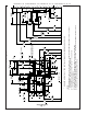
4) With the power cord, waterline and reset button wires through the hole on top of water cooler place Bottle Filler on to mounting bracket on basin.
(See Fig. 3). Make sure bottle ller is installed properly on the basin gasket.
5) Once Bottle Filler is installed on basin mounting bracket, tighten the two screws (supplied) one on each side of the bottle ller. Install Top Cover on Bottle
Filler (See FIG. 3) with two mounting screws (supplied) . Caution do not over tighten screws.
6) For Two Level Model Installations: Secure non-refrigerated unit to wall, connect drains and water inlet. Connect black reset button wires from
non-refrigerated unit to the black wires on the refrigerated unit (see step 4).
7) For Single Model Installations: Install remaining tube insulation to the water line from bottle ller, connect Bottle Filler waterline inside of the water cooler
by connecting the 3/8” water line with the 3/8” to 1/4” union and short piece of poly tube that was previously installed to the tee at the evaporator outlet.
7a) For Two Level Model Installations: Install the 1/4” poly tubing and insulation from the outlet of the lter to the union on top of the evaporator. Install the
1/4” poly tubing and insulation from the regulator in the non-refrigerated cooler to one of the tees at the evaporator outlet. Install remaining tube insulation
to the water line from bottle ller, connect Bottle Filler waterline inside of the water cooler by connecting the 3/8” water line with the 3/8” to 1/4” union and
short piece of poly tube that was previously installed to the tee at the evaporator of the refrigerated cooler.
8) Install lter cartridge, remove lter from carton, remove protective cap, attach lter to lter head by rmly inserting into head and rotating lter clockwise.
NOTE: If existing plumbing rough-in locations (Drain, Water In, Electric Supply) do not allow the lter to be mounted inside the cooler cabinet
the lter can be installed horizontally below the unit. A retrot kit is available to mount the lter beneath the cooler.
9) Turn water supply on and inspect for leaks. Fix all leaks before continuing.
10) Once unit has been inspected for leaks and any leaks found corrected, plug Bottle Filler and LVRC unit into wall. Be sure to reinstall fuse to the circuit
or switch the circuit breaker back to the “ON” position.
11) Once power is applied to Bottle Filler, the GREEN LED light should illuminate showing good lter status along with the LCD Bottle Counter.
12) Verify proper dispensing by depressing the button at the top of the Bottle Filler and verify water dispenses. Note: the rst initial dispenses
might have air in line which may cause a sputter. This will be eliminated once all air is purged from the line.
14) Once unit tests out, install Lower Panel back on LVRC water cooler(s). Units are now ready for use.
MOUNTING BRACKET
FOR FASTENING UNIT
TO WALL
TOP COVER
MOUNTING
SCREWS
Fig. 3
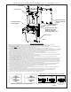
MOUNTING SCREWS
DO NOT REMOVE
MOUNTING SCREWS
DO NOT REMOVE
BOTTLE FILLER
WATER COOLER
NOTE: TRIM PLATES MUST
BE INSTALLED ON THE
INSIDE OF THE BOTTLE
FILLER SIDE PANEL SLOTS.
B CA
SIMPLY PUSH IN
TUBE TO ATTACH
TUBE IS SECURED
IN POSITION
PUSH IN COLLET
TO RELEASE TUBE
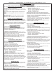
OPERATION OF QUICK CONNECT FITTINGS
PUSHING TUBE IN BEFORE
PULLING IT OUT HELPS TO
RELEASE TUBE
OPERATION OF QUICK CONNECT FITTINGS
SIMPLY PUSH IN
TUBE TO ATTACH
TUBE IS SECURED
IN POSITION
PUSH IN COLLET
TO RELEASE TUBE
PUSHING TUBE IN BEFORE
PULLING IT OUT HELPS TO
RELEASE TUBE
A B C