
Installation Sheet


Page 698980C (Rev. G- 01/15)
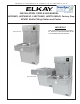
LVRCDWS*A, *2A LVRCTLDDWSC*A, *2A LVRC8WS*1A, *2A, *3A LVRCTL8WSC*1A, *2A, *3A
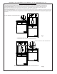
STANDARD TWO-LEVEL CONFIGURATION
STANDARD TWO-LEVEL REVERSED CONFIGURATION
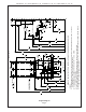
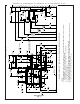
1/4” HEX. HEAD BOLT THIS LOCATION ONLY
REMOVAL OF BOTTLE FILLER FOR SERVICING
1) Turn off the water supply to the Water Cooler(s). Unplug and/or turn off Circuit Breaker to Cooler(s) and Bottle Filler. NOTE: the Lower Front Panel
of the cooler(s) may need to be removed. To prevent scratching the basin place a towel or soft cloth over the entire basin when working above it.
2) For Single Model Installations: Loosen but DO NOT remove the two (2) Pinned Torx Head Screws from the sides of the Bottle Filler. Remove the
two (2) Pinned Torx Head Screws from the Top Cover & remove the Top Cover. The Bottle Filler may then be lifted up and off the Water Cooler
(The water line and Remote Reset Button Wires will still be connected from the Water Cooler to the Bottle Filler.).
3) For Two Level Model Installations: Loosen but DO NOT remove the Pinned Torx Head Screw from the outer side of the Bottle Filler and loosen but DO NOT remove
the 1/4” hex. head bolt from between the two cooler (See Figs 6 or 7). Remove the two (2) Pinned Torx Head Screws from the Top Cover & remove the Top Cover.
The Bottle Filler may then be lifted up and off the Water Cooler (The water line and Remote Reset Button Wires will still be connected from the Water Cooler to the
Bottle Filler.).
Fig. 6
Fig. 7
1/4” HEX. HEAD BOLT THIS LOCATION ONLY