
Installation Sheet

Page 4
LZO8*1G LZO8*2G LZO8*3G LZOD*1D
1000003094 (Rev. D - 11/16)
HANGER BRACKETS & TRAP
INSTALLATION
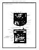
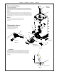
1) Remove hanger bracket fastened to back of cooler by removing one (1) screw.
2) Mount the hanger bracket as shown in Figure 2.
NOTE: Hanger Bracket MUST be supported securely. Add xture support carrier if wall will not provide adequate support. Anchor hanger
securely to wall using all six (6) 1/4 in. dia. mounting holes.
IMPORTANT:
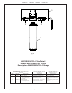
5-7/8 in. (150mm) dimension from wall to centerline of trap must be maintained for proper t.
INSTALLATION OF COOLER
3) Hang the cooler on the hanger bracket. Be certain the hanger bracket is engaged properly in the slots on the cooler back as shown
in Figure 2.
4) Remove the four (4) screws holding the lower front panel at the bottom of cooler. Remove the front panel by pulling straight down
and set aside.
5) Connect water inlet line--See Note 4 of General Instructions.
6) Install trap. Remove the slip nut and gasket from the trap and install them on the cooler waste line making sure that the end of the
waste line ts into the trap. Assemble the slip nut and gasket to the trap and tighten securely.
IMPORTANT: If it is necessary to cut the drain, loosen the screw at the black rubber boot and remove tube, check for leaks after re-assembly.
7) Plug in electrical power. Unit must have
electrical power to have water ow.
START UP
Also See General Instructions
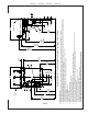
8) Stream height is factory set at 35 PSI. If supply pressure varies greatly from this, adjust screw located on the left side below
the push bar assembly on the crossbar. CW adjustment will raise stream and CCW adjustment will lower stream. For best
adjustment, stream should hit basin approximately 6-1/2” (165mm) from bubbler on the downward slope of the basin.
NOTE: If continuous ow occurs at the end of the compressor cycle, turn cold control counterclockwise 1/4 turn.
9) Replace the front panel ensuring that the metal wrapper is secured inside of the upper shroud. Replace all four screws previously
removed.
SENSOR RANGE ADJUSTMENT:
The electronic sensor used in this cooler is factory pre-set for a “visual” range of 36 inches (914 mm). If actual range varies greatly
from this or a different setting is desired, follow the range adjustment procedure below:
- Using a small tip screwdriver, locate range adjustment screw through the small hole between the sensor
lenses (See Page 1.) Turn this screw clockwise to increase range and counterclockwise to decrease range
(See Fig. 3).
CAUTION: Complete range of sensor (24-36 inches/610-1168mm) is only one turn of the adjusting screw.
SENSOR WITH VISUAL FILTER MONITOR (VFM) – LZO SERIES:
The electronic sensor includes LED lter status indicators that are factory preset to monitor lter life. The sensor monitors the “ON”
time of the water valve solenoid and keeps track of total time water is dispensed. There are (3) LED’s and indicates the following:
Green LED (Good) indicates that the lter is operating within 0% - 80% of its life.
Yellow LED indicates that the lter is operating within 80% - 100% of its life.
Red LED (Replace) indicates that the lter needs to be replaced since it has reached end of lter life.
Once power is applied to the water cooler, if all three LED’s ash then the Green LED illuminates, this indicates that there is some lter
usage memory stored. When the Green LED comes on only, this indicates that the lter life is at absolute 0% of lter life. NOTE: You
may have some very minimal lter life in memory upon receiving water cooler due to factory functional testing.
NOTE: The lter status will be retained until reset (see resetting lter monitor). The lter monitor will retain its memory even
during a loss of power.
RESETTING VISUAL FILTER MONITOR (VFM):
In order to reset the visual lter monitor status LED’s, you must remove the access panel (item 13) underneath the front dispenser.
With your nger or straight blade screw driver, reach inside opening and depress the reset button located on the back of the sensor for
a minimum of 1 second. (You may need a ashlight) Reinstall access panel and the Green LED should be illuminated indicating that
the visual lter monitor has been reset.
SENSOR CONTROL: If sensor fails to operate valve mechanism or operates erratically, check the following.
A. Ensure there are no obstructions within a 40 inch (1016mm) radius in front of cooler.
B. Check wire connections at the solenoid valve and sensor. CAUTION: Make sure unit is unplugged before checking any wiring.
C. Ensure proper operation of solenoid valve. If there is an audible clicking sound yet no water ows, look for an obstruction in the
valve itself or elsewhere in the water supply line.