
Installation Sheet


Service Instructions
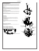
Lower and Upper Shroud
To access the refrigeration system and plumbing connections, remove four screws from bottom
of cooler to remove the lower shroud. To remove the upper shroud for access to the pushbars,
regulator, solenoid valve or other components located in the top of the unit, remove lower shroud,
disconnect drain, remove four screws from tabs along lower edge of upper shroud, unplug two
wires and water tube.
Bubbler
To remove the bubbler, rst disconnect the power supply. The underside of the bubbler can be
reached through the access panel on the underside of the upper shroud. Remove the access
panel by removing the retaining screw. To remove the bubbler, loosen locknut from the underside
of the bubbler and remove the tubing from the quick connect tting per the Operation Of Quick
Connect Fittings section in the General Instructions. After servicing, replace the access panel
and retaining screw.
Switches Behind the Push Bar
The regulator in an EZ cooler is always held fully open by the use of a single regulator nut (See
Item 9, Fig. 15). Water is not dispensed until the pushbar is depressed to activate a switch which
then opens a solenoid valve.
To remove sidebars, from the inside compress the ared tabs and pull out carefully. To reinstall
side pushbars, the front of the pushbar is inserted rst. While keeping the switch depressed,
snap the rear of the pushbar into position.
Cleaning
Stainless Steel
• General cleaning: use an ordinary mild detergent and soft cloth, rinse and towel dry.
• Steel soap pads should never be used; particles can adhere to a stainless steel basin
surface and will eventually rust.
• Light scratches are normal for stainless steel basins; over time they will blend into the
uniform nish pattern.
Plastic Components
• General cleaning: use an ordinary mild detergent and soft cloth, rinse and towel dry.
• Wiping the surface clean to remove debris or build up will not hurt the antimicrobial
properties.
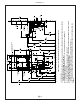
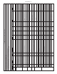
Fig. 15
Fig. 15
Temperature Control
• Factory set at 50°F (+/- 5°F) under normal conditions. For temperature adjustments, refer to
sticker on left side of top bar.
Stream Height Adjustment
VIEW OF UNDERSIDE OF BASIN SHROUD
Stream Height Adjustment Location
SNAP
SNAP
REGULATOR
ASSEMB LY
ALIGNMENT
PEG
ALIGNMENT
NOTCH
11
2
12, 13
6
12
19
22
22
9
8
11
Page 8
ENLZS8WS_1G
1000004538 (Rev. C - 07/19)