EZSTLDWS*1D EZSTLRDWS*1D EZSTL8WS*1D, 2D, 3D EZSTLR8WS*1D LZSTLDWS*1D LZSTLRDWS*1D LZSTL8WS*1D, 2D, 3D LZSTLR8WS*1D INSTALLATION, CARE & USE MANUAL Manual de Instalación, Cuidado y Utilización Manuel d’installation/entretien/utilisation EZ ™ & LZ™ Series Versatile Bottle Filling Stations & Coolers EZ™ & LZ™ Serie versatil Botella Bombas y Enfriadores EZ™ & LZ™ Stations versatile de Remplissage de Bouteille Série et Refroidisseurs *Versatile Cooler Model LZSTL8WSLK alternate installations *Versatile Coole
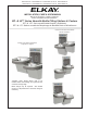
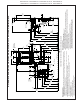
EZSTLDWS*1D EZSTLRDWS*1D EZSTL8WS*1D, 2D, 3D EZSTLR8WS*1D LZSTLDWS*1D LZSTLRDWS*1D LZSTL8WS*1D, 2D, 3D LZSTLR8WS*1D Pictured is unit only without bottle filler. Uses HFC-R134A refrigerant Usa refrigerante HFC-R134A Utilise du fluide frigorigéne HFC-R134A 1 31 20 1 24 14 15 21 16 6 5 5 12 6 3 3 2A See Fig. 9 12 See Fig. 9 2B 19 19 12 13 16 27 22 7 19 19 18 19 23 Fig. 1 1000001733 (Rev.
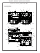
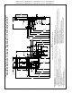
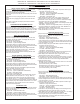
Page 3 D PREFERRED 24 1/2" LOCATION 622mm 22 15/16" 583mm 19 7/16" 494mm 34 5/16" 872mm F E OPTIONAL FILTER A (ALT. LOCATION) ‰ B 7" 178mm 2" 51mm A PREFERRED LOCATION 6 3/8" 162mm FINISHED FLOOR 3 7/8" 98mm 5 3/4" 146mm 7" 178mm 6 3/8" 162mm 7" 178mm 28 13/16" 732mm FIG.
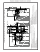
1000001733 (Rev. C - 8/14) Page 4 E B 15" 381mm A (ALT. LOCATION) 3 7/8" 98mm ‰ 7" 178mm ‰ 7" 178mm 5 3/4" 146mm 2" 51mm 6 3/8" 162mm FIG. 3 FINISHED FLOOR D (ALT.
Page 5 E B A (ALT. LOCATION) 3 7/8" 98mm 6 3/8" 162mm ‰ 7" 178mm FINISHED FLOOR D (ALT. LOCATION) 7" 178mm 5 3/4" 146mm 2" 51mm 6 3/8" 162mm FIG.
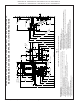
1000001733 (Rev. C - 8/14) Page 6 E F OPTIONAL FILTER A (ALT. LOCATION) 2 7/8" 73mm 15" 381mm D PREFERRED LOCATION 7" 178mm ‰ B E 28 13/16" 732mm 2" 51mm 21 7/8" F 19" 556mm 483mm FIG.
EZSTLDWS*1D EZSTLRDWS*1D EZSTL8WS*1D, 2D, 3D EZSTLR8WS*1D LZSTLDWS*1D LZSTLRDWS*1D LZSTL8WS*1D, 2D, 3D LZSTLR8WS*1D HANGER BRACKETS INSTALLATION 1) Remove hanger brackets fastened to back of cooler by removing one (1) screw. 2) Mount the hanger brackets as shown in Figures 2, 3, 4 or 5. NOTE: Hanger Bracket MUST be supported securely. Add fixture support carrier if wall will not provide adequate support. Anchor hanger securely to wall using all six (6) 1/4 in. dia. mounting holes.
EZSTLDWS*1D EZSTLRDWS*1D EZSTL8WS*1D, 2D, 3D EZSTLR8WS*1D LZSTLDWS*1D LZSTLRDWS*1D LZSTL8WS*1D, 2D, 3D LZSTLR8WS*1D Service Instructions Lower and Upper Shroud To access the refrigeration system and plumbing connections, remove four screws from bottom of cooler to remove the lower shroud.
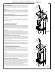
EZSTLDWS*1D EZSTLRDWS*1D EZSTL8WS*1D, 2D, 3D EZSTLR8WS*1D LZSTLDWS*1D LZSTLRDWS*1D LZSTL8WS*1D, 2D, 3D LZSTLR8WS*1D 7/16” BOLT HOLES FOR FASTENING UNIT TO WALL UNIT CENTER LINE TOP COVER Fig. 8 MOUNTING SCREWS 30 Fig. 9 Fig. 10 Fig. 11 BRACKET, WASHERS, & SCREWS Bottle Filler Installation Instructions 1) Remove two (2) mounting screws with 5/32” Allen wrench holding top cover to Bottle Filler (See Fig. 9). Remove top cover.
EZSTLDWS*1D EZSTLRDWS*1D EZSTL8WS*1D, 2D, 3D EZSTLR8WS*1D LZSTLDWS*1D LZSTLRDWS*1D LZSTL8WS*1D, 2D, 3D LZSTLR8WS*1D BF11 PROGRAM SETTING THE CONTROL BOARD VERIFY CONTROL BOARD SOFTWARE 1) To verify the software program of the control board the unit will need to be shut down and restarted. The chiller (if present) does not need to be shut down and restarted. 2) The units lower panel must be open to access the power cord and wall outlet.
EZSTLDWS*1D EZSTLRDWS*1D EZSTL8WS*1D, 2D, 3D EZSTLR8WS*1D LZSTLDWS*1D LZSTLRDWS*1D LZSTL8WS*1D, 2D, 3D LZSTLR8WS*1D INSTRUCTIONS TO MOVE THE BOTTLE FILLER & BASIN TO THE LEFT SIDE (NON-REFRIGERATED) FOR ALTERNATE MOUNTING VERSATILE BI-LEVEL Using a 5/16" socket, remove the (4) screws from the bottom of each cooler to remove the wrappers. Using a #T20 (6 point star bit), loosen the shroud screws. Both sides, both coolers.
EZSTLDWS*1D EZSTLRDWS*1D EZSTL8WS*1D, 2D, 3D EZSTLR8WS*1D LZSTLDWS*1D LZSTLRDWS*1D LZSTL8WS*1D, 2D, 3D LZSTLR8WS*1D INSTRUCTIONS CONTINUED..... Swap drain parts in shroud: Loosen each hose clamp retaining the drain pieces. Remove each drain piece and swap to other basin. Tighten each hose clamp. Refrigerated Cooler side: Carefully tip the shroud/basin assembly toward the cooler frame. Connect one of the black wires to the solenoid valve and one wire to the cold control.
EZSTLDWS*1D EZSTLRDWS*1D EZSTL8WS*1D, 2D, 3D EZSTLR8WS*1D LZSTLDWS*1D LZSTLRDWS*1D LZSTL8WS*1D, 2D, 3D LZSTLR8WS*1D Versatile Wrapper and Trim Kit Installation Instructions Left Hand Wrapper (High Side) 1) Remove existing wrapper by removing the (4) screws from bottom. 2) Screw trim piece to wrapper with (2) screws (provided) 3) Re-install wrapper with (4) screws. 4) Dispose of unused Right Hand Wrapper (Low Side) 1) Remove existing wrapper by removing the (4) screws from bottom.
EZSTLDWS*1D EZSTLRDWS*1D EZSTL8WS*1D, 2D, 3D EZSTLR8WS*1D LZSTLDWS*1D LZSTLRDWS*1D LZSTL8WS*1D, 2D, 3D LZSTLR8WS*1D PLUMBING DIAGRAMS VERSATILE BI-LEVEL Barb capped when not used Bottle Filler Drain Bottle Filler Drain Barb capped when not used Bottle Filler Drain Barb capped when not used Bottle Filler Drain Barb capped when not used 1000001733 (Rev.
Solenoid Valve Tee Solenoid Valve 3/8” Water Inlet Evaporator 3/8” Water Line from Bottle Filling Unit R.H. Refrig. unit EZ Bi-Level Plumbing Diagram after Filter Installation & Bottle Filler Water Line Addition H Water Inlet Bubbler L.H. Non-Refrig unit Page 15 Solenoid Valve H Tee 1/4” Union Filter Assembly Bubbler L.H. Non-Refrig unit 3/8” Water Inlet Bubbler Standard EZ Bi-Level Pressurized Plumbing Diagram Solenoid Valve Evaporator R.H. Refrig.
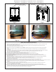
EZSTLDWS*1D EZSTLRDWS*1D EZSTL8WS*1D, 2D, 3D EZSTLR8WS*1D LZSTLDWS*1D LZSTLRDWS*1D LZSTL8WS*1D, 2D, 3D LZSTLR8WS*1D NOTE: When installing replacement bubbler and pedestal, tighten nut only to hold parts snug in position. Do Not Overtighten. 11 NOTA: Al instalar el grifo y pedestal de reemplazo, apriete la tuerca unicamente para mantener las piezas en una posicion adjustada. No dede apretarse demasiado.
EZSTLDWS*1D EZSTLRDWS*1D EZSTL8WS*1D, 2D, 3D EZSTLR8WS*1D LZSTLDWS*1D LZSTLRDWS*1D LZSTL8WS*1D, 2D, 3D LZSTLR8WS*1D OPERATION OF QUICK CONNECT FITTINGS SIMPLY PUSHIN IN SIMPLY PUSH TUBE TO TUBE TOATTACH ATTACH A A TUBE TUBEIS IS SECURED SECURED INPOSITION POSITION IN PUSH PUSHIN IN COLLET COLLET TORELEASE RELEASE TUBE TUBE TO B C PUSHING BEFORE PUSHINGTUBE TUBE IN IN BEFORE PULLING TO PULLING IT IT OUT OUT HELPS HELPS TO RELEASE RELEASE TUBE TUBE Note: Screw the locknut hand tight to seal Fig.
EZSTLDWS*1D EZSTLRDWS*1D EZSTL8WS*1D, 2D, 3D EZSTLR8WS*1D LZSTLDWS*1D LZSTLRDWS*1D LZSTL8WS*1D, 2D, 3D LZSTLR8WS*1D Switch Activation Note: Only side push activation is shown. Front push works the same. Detalle de la activación del interruptor Nota: Lateral presion activación que se muestran. Frontal presion es la similar. Description de l’activation de l’interrupteur Remarque: Laterel puossoir activación que des indique. Face puossoir des semblable.
EZSTLDWS*1D EZSTLRDWS*1D EZSTL8WS*1D, 2D, 3D EZSTLR8WS*1D LZSTLDWS*1D LZSTLRDWS*1D LZSTL8WS*1D, 2D, 3D LZSTLR8WS*1D ITEM NO. 1 2A 2B 3 *4 5 6 7 8A 8B 9 10 11 12 13 14 15 16 17 18 19 20 21 22 23 24 25 26 27 28 29 30 31 NS NS NS PART NO.
EZSTLDWS*1D EZSTLRDWS*1D EZSTL8WS*1D, 2D, 3D EZSTLR8WS*1D LZSTLDWS*1D LZSTLRDWS*1D LZSTL8WS*1D, 2D, 3D LZSTLR8WS*1D This page intentionally left blank 1000001733 (Rev.