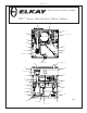
VRC8FR*1C INSTALLATION, CARE & USE MANUAL VRC TM Series Barrier-Free Water Coolers Uses HFC-134A refrigerant 10 20 38, 39 54 6, 7, 22, 41 51 50 42 42 16 59, 60 1, 4 23, 61, 62 25 See Fig. 4 See Fig. 3 45 45 24, 30 21 21 21 63 43 21 8 19 33 11 49 32 55 Fig. 1 21 37 9, 12, 13 2, 3, 5 Page 1 98966C (Rev.
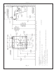
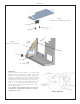
Fig. 2 98966C (Rev. B - 2/13) Page 2 F = 7/16 BOLT HOLES FOR FASTENING UNIT TO WALL E = INSURE PROPER VENTILATION BY MAINTAINING 6" (152 mm) (MIN.) CLEARANCE FROM CABINET LOUVERS TO WALL. D = ELECTRICAL SUPPLY (3) WIRE RECESSED BOX C = 1-1/4 TRAP NOT FURNISHED** B = RECOMMENDED LOCATION FOR WASTE OUTLET 1-1/4” O.D. DRAIN LEGEND/LEYENDA/LÉGENDE A = RECOMMENDED WATER SUPPLY LOCATION. SHUT OFF VALVE (NOT FURNISHED) TO ACCEPT 3/8” O.D. UNPLATED COPPER TUBE.
VRC8FR*1C IMPORTANT ALL SERVICE TO BE PERFORMED BY AN AUTHORIZED SERVICE PERSON HANGER BRACKETS & TRAP INSTALLATION 1 ) Remove hanger bracket fastened to back of cooler by removing one (1) screw. 2 ) Mount the hanger bracket and trap as shown in Figure 2. NOTE: Hanger Bracket MUST be supported securely. Add fixture support carrier if wall will not provide adequate support. IMPORTANT: y 6 1/4 in. (159mm) dimension from wall to centerline of trap must be maintained for proper fit.
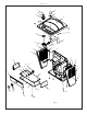
VRC8FR*1C 61 15 62 1 23 25 45 (8) 30 1 4 50 24 60 46 53 33 59 31 46 31 35 53 32 14,17,18 48 40 46 44 36 26 46 52 28 27 34 47 (4) 29 45 (6) 46 46 Fig. 4 98966C (Rev.
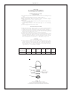
VRC8FR*1C Fig. 5 Thermostat Installation Detail 56 21 21 57 Fig. 6 Heater Strip Detail 54 58 55 58 45 WARNING! This unit is frost resistant down to 0° F with no wind. Prevailing winds can reduce the ability of the heater element to prevent light freezing. If the ambient air temperature will drop below 0° F, the cooler needs to be drained of all water by blowing out all water lines, evaporator (item 20), and the drain trap.
VRC8FR*1C 115V PARTS LIST ITEM NO. PART NO.