98086010 Rev-C (ECN 120227) IMPORTANT Pass Instructions On To End User
Table of Contents I. PRODUCT SAFETY ……………………………………………………3 II. SYSTEM DISCRIPTION ……………………………..…………………4 III. VALVE OPERATION …………………………………………………..4 A. AUTO TRAVEL: …………………………………………………….4 B. INDICATOR LIGHT SIGNALS …………………………………….5 C. OTHER CONTROL FEATURES ……………………………………5 IV. ELECTRICAL SPECIFICATIONS ………………………………………6 V. INSTALLATION INSTRUCTIONS ……………………………………..6 A. VALVE INSTALLATION ……………………………………………6 B. VALVE CONTROLLER AND POSITION INDICATOR …………..9 C. INTERCONNECTING HARNESSES ……………………………..
I. PRODUCT SAFETY: It is critical to the safety of installers, users and bystanders that the following precautions are followed: 1. Keep fingers and hands clear of the valve waterway whenever power is connected to the valve. 2. Be certain that the valve motor power is disconnected prior to servicing the valve. Motor power can be disconnected by pulling apart the small, twoconductor automotive type wire connector near the valve motor. 3.
II. SYSTEM DESCRIPTION: The 2900E series electrically actuated valve line includes a complete range of ball valve sizes including 1-1/2”, 2”, 2-1/2”, 3”, and 4”, and butterfly valves in 2”, 3”, 4”, 5”, and 6” sizes. The valve opening and closing actions are controlled by a bronze worm gear case driven by a 12 volt DC gear motor.
B. Indicator Light Signals: The valve controller/position indicator module (81384001) uses three high intensity LED’s, red, amber, and green, for reliable status indication under all ambient lighting conditions.
IV. ELECTRICAL SPECIFICATIONS: Valve Type 3” and 4” Ball Valves All Butterfly Valves Nominal Operating Voltage Operating Voltage Range 1.5”, 2.0”, and 2.5” Ball Valves 12 VDC 11-15 VDC (RECOMMENDED FUSE RATING 10A) Normal Operating Current 3A 1.5 A Motor Stall Current 13 A 11.9 A Operating Temperature Range -40°F to 150°F V. INSTALLATION INSTRUCTIONS: A. Valve Installation: The 2900E ball valves sizes 1.5” through 3.0” are bi-directional and can be installed in either direction. The 2940E 4.
NOTE: Valve actuators should be positioned to provide best access to the ¾” hex manual override nut. Ball Valves; 1. Place the valve in the fully closed position. Note that the slot in the end of the actuator shaft shows the position of the ball. When the slot is at a right angle to the waterway, the valve is fully closed. 2. Remove the four socket head cap screws from the gear case cover, and then pull the cover from the gear case. Rotating the cover slightly will ease removal. 3.
6. Apply Loctite #242 to the four screws and reinstall them to secure the gear case to the valve body. Torque the screws to 120-150 in-lbs. 7. Install the gear segment in the correct position as shown in Figure 1 above. Note that rotating the worm slightly will ease gear segment installation. 8. Apply petroleum base grease to the thrust washer and install. 9. Reassemble the gear case cover on the gear case taking care not to damage the cover O-ring. 10.
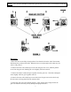
B. Valve Controller and Position Indicator Module: The 81384001 valve controller and position indicator module is to be installed in the pump control panel. The panel cutout template is shown on the layout drawing. The module is secured to the pump panel with four split lock washers and four #6-32 stainless steel small pattern nuts (1/4” socket driver), which are provided with the module. The pressure gage for each discharge valve should be installed above the 81384001 module controlling that valve.
VI.
VII.
12