
Instruction Manual


E
E
L
L
K
K
H
H
A
A
R
R
T
T
B
B
R
R
A
A
S
S
S
S
M
M
F
F
G
G
.
.
C
C
O
O
.
.
,
,
I
I
N
N
C
C
.
.
1302 WEST BEARDSLEY AVENUE • P.O. BOX 1127 • ELKHART IN 46515 • (574) 295-8330 • FAX (574) 293-9914
98434001 REV. REL
Detailed Installation Instructions For Bumper Replacement
All Nozzles Except SM-3 Series and 4000-01 Series
Step 1: Locate and remove the two indicator sleeve screws by using
a #10 Torx bit as shown in Figure 1. After removing the screws,
turn the tip of the nozzle counter-clockwise until it threads off of the
nozzle body. Remove the bumper by cutting it off with a utility
knife. Caution – Secure nozzle tip before cutting off bumper.
Step 2: See Table 1 to determine which side of the tooth guard
should be facing up for the nozzle being repaired. Thread the tooth
guard and two hex nuts onto the threaded rod as shown in Figure 2.
Slide the expansion cone (also determined from Table 1) down onto
the opposite end of the threaded rod until it rests into the back side
of the nozzle tip as shown in Figure 2.
Step 3: Place the replacement bumper on the expansion cone with
the threaded rod through the center of it. A soap and water
solution should be applied to the inside of the bumper as a
lubricant. Be sure to line up the slots on the inside of the
bumper with the screws protruding from the front of the nozzle
tip. Determine the correct push tube to be used from Table 1 and
slide it down over the bumper. Use Table 1 to determine which side
of the drive plate should be facing up and slide it down on the
threaded rod until it comes to rest on top of the push tube. Slide a
thrust washer, thrust bearing, and another thrust washer onto the end
of the threaded rod until they rest on the drive plate. Thread the
remaining hex nut down onto the threaded rod until it rests on the
top thrust washer.
Step 4: Hold the bottom set of hex nuts stationary by using either a
vice or a wrench. Turn the top hex nut clockwise with a wrench to
force the bumper down until it is flush with the end of the nozzle
tip. Turn the top hex nut counter-clockwise until it is off the
threaded rod. Pull the bumper kit apart and reattach the nozzle tip to
the nozzle body. Do not forget to re-insert indicator sleeve screws.
Table 1
NOZZLE
TYPE
EXPANSION
CONE
PUSH
TUBE
TOOTH GUARD
SIDE UP
DRIVE PLATE
SIDE UP
SM-3 SERIES
4000-01 SERIS
N/A N/A 1 1
SM-10 & SM-20 SERIES
4000-10 SERIES
SMALL SMALL 1 2
SM-30 SERIES
4000-20 SERIES
LARGE LARGE 2 1
4014
4000-20LP
SMALL SMALL 2 2
Figure 1
Location of Indicator Sleeve Screws
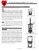
Figure 2
Bumper Replacement Assembly Configuration
INDEX
NO.
DESCRIPTION
QUANTITY
PER UNIT
1 Hex Nut 3
2 Tooth Guard 1
3 Threaded Rod 1
4 Nozzle Tip 1
5 Expansion Cone 2
6 Bumper 1
7 Push Tube 2
8 Drive Plate 1
9 Thrust Washer 2
10 Thrust Bearing 1