
User guide


1
ELKHART BRASS MANUFACTURING COMPANY
INSTALLATION and OPERATING INSTRUCTIONS
for
PRESSURE-MATIC®
AUTOMATIC PRESSURE REDUCING VALVES
I. Models and Sizes Covered:
UR-20, 1-1/2" size, bonnet types W,X,Y,YZ,Z,ZA,ZB,ZZ & ZZA
UR-25, 1-1/2" size, bonnet types W,X,Y,YZ,Z,ZA,ZB,ZZ & ZZA
UR-20, 2-1/2" size, bonnet types A,B,C,CD,D,DE,E,EF & F
UR-25, 2-1/2" size, bonnet types A,B,C,CD,D,DE,E,EF & F
UR-20S, 2-1/2" size, bonnet types A,B,C,CD,D,DE,E,EF & F
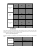
Inlet and Outlet Connections:
Valve Model & Size
*Inlet Thread
*Outlet Thread
UR-20, 1-1/2"
1-1/2" fem. NPT
1-1/2" fem. NPT
UR-25, 1-1/2"
1-1/2" fem. NPT
1-1/2" male NH
UR-20, 2-1/2"
2-1/2" fem. NPT
2-1/2" fem. NPT
UR-25, 2-1/2"
2-1/2" fem. NPT
2-1/2" male NH
UR-20S, 2-1/2"
2-1/2" fem. NPT
2-1/2" fem. NPT
*NPT = American National Standard Taper Pipe Threads (ANSI/ASME B1.20.1-1983, R2006)
NH = American National Fire Hose Connection Screw Thread (NFPA 1963-2009 Ed.)
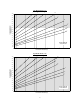
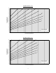
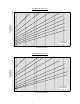
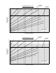
II. Application Guidelines:
A. Automatic Sprinkler Systems
Pressure-Matic® valves are most commonly used in automatic sprinkler systems as floor control valves in high-
rise buildings where supply riser pressures exceed 175 psi. These valves are listed by Underwriters Laboratories
as Special System Water Control Valves-Pressure Reducing and Pressure Control Type (VLMT), and also meet
the listing requirements for indicating valves. Requirements for the installation of pressure reducing valves in
automatic sprinkler systems are given in Section 4-6.1.2 of NFPA 13, Standard for the Installation of Sprinkler
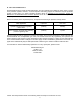
Systems, Latest Edition. When designing Pressure-Matic® valves into a sprinkler system, the following maximum
flow rate limits should be observed:
98278000 Rev
B