
User guide


3
For proper installation of bracket and switch, see instruction sheet which accompanies bracket kit, and also refer
to switch manufacturer's instructions.
Sprinkler System Installation Requirements
1. To permit easy replacement or repair of valve, pipe unions or rubber gasketed mechanical couplings should be
installed immediately upstream or downstream of the valve.
2. A relief valve of not less than 1/2 inch size is to be installed on the downstream side of each Pressure-Matic®
valve.
3. Pressure gauges are to be installed on the inlet and outlet sides of each pressure reducing valve.
4. Valve type should be selected to provide an outlet pressure not exceeding 165 psi at the maximum inlet
pressure.
5. Upon system completion, each Pressure-Matic® valve must be tested under both flow and no-flow conditions
to verify that static and residual outlet pressures and flow rates satisfy system design requirements, per
requirements of Section 8-2.5 of NFPA 13.
B. Standpipe System Applications
With their male hose thread outlet connections, the model UR-25 valves are intended for use as pressure
reducing hose valves in standpipe systems. When hose racks are used, the UR-20 valves can be utilized along
with a special hose nipple for support of the rack. The Pressure-Matic® valves are listed by Underwriters
Laboratories as Standpipe Equipment Pressure Reducing Devices (VUTX). Requirements for the installation of
pressure reducing valves in standpipe systems are given in Section 5-8 of NFPA-14, Standard for the Installation
of Standpipe and Hose Systems, Latest Edition. The 2-1/2" UR-25 can be used for both Class I and Class III
service, while the 1-1/2" version can used for Class II systems. NFPA 14 requires that hose valve outlet pressure
for Class I and Class III service be no greater than 175 psi, and no less than 100 psi. When permitted by the
authority having jurisdiction, pressures less than 100 psi may be allowed, but in no case shall the valve discharge
pressure be less than 65 psi. Class II hose valves must be limited to a maximum residual outlet pressure of 100
psi, but the minimum outlet pressure shall not be less than 65 psi.
Acceptance Tests
Upon completion of system, each Pressure-Matic® hose valve shall be tested in accordance with paragraph 8-5.5
of NFPA 14 to verify that the installation is correct, that the valves are operating properly, and that the inlet and
outlet pressures at the valve are in accordance with the design.
III. Valve Performance Characteristics & Limitations:
A. Valve Construction & Operating Principle
The Pressure-Matic® is a fairly simple pressure reducing valve, which utilizes a hydraulic piston and cylinder
assembly within the valve bonnet to allow the valve to self-throttle in response to the pressure on the downstream
side of the valve. Because the piston, main stem and valve seat float freely from the manual valve stem and
handwheel assembly, the valve is able to self-close under static conditions, and maintain a reduced pressure
under no-flow conditions, as well as under flowing conditions. Valve discharge pressure is transmitted to the top
side of the piston through pressure passages in the main stem. The presence of the piston results in a net area
differential which produces a hydraulic balancing force in the closed direction. The magnitude of this balancing
force is in direct proportion to the hydraulic area of the piston.
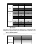
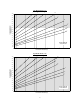
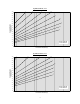
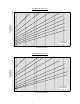
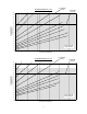
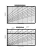
The Pressure-Matic® is a non-adjustable pressure reducing valve design, which means that the pressure
reduction ratio of a given valve cannot be varied. However, the valves are available with any of nine (9) different
piston diameters in order to satisfy all expected inlet/outlet pressure ratios. The valve piston size is designated by
a "type" letter, ranging from "A" through "F" for the 2-1/2" valves, and from "W" through "ZZA" for the 1-1/2"
valves. Each valve "type" then provides a fixed pressure reduction ratio, meaning that the outlet pressure will
always be a fixed percentage of the inlet pressure, regardless of inlet pressure. It should be noted, however, that