Industrial Electric Operator Control Panel For use with Model 8394053 SPIT-FIRE® Monitor Setup Instructions 98348000 REV. E 1302 WEST BEARDSLEY AVENUE • P.O. BOX 1127 • ELKHART IN 46515 • (574) 295-8330 • FAX (574) 293-9914 © 2012 ELKHART BRASS MFG. CO., INC.
PRODUCT SAFETY Important: Before installing and operating this equipment, read and study this manual thoroughly. Proper installation is essential to safe operation. In addition, the following points should be adhered to in order to ensure the safety of equipment and personnel: • All personnel who may be expected to operate this equipment must be thoroughly trained in its safe and proper use.
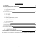
TABLE OF CONTENTS I. OVERVIEW 4 II. SYSTEM CONFIGURATION INSTRUCTIONS • Example Network • Network Parameter Worksheet • OCP Layout III. SETUP INSTRUCTIONS • Setup of LOCP • Setup of ROCP • Setup of NCP • Changing 50 / 60 Hz Monitor Operations • Adding MMCP Power On indication • Monitor Auto Daily Exercise • Setup for Auxiliary Inputs 7 10 IV. SPECIFICATIONS 18 V. MAINTENANCE 18 VI. TROUBLESHOOTING 19 VII.
I OVERVIEW NOTE TO ALL USERS: • This manual was written with a dual monitor Operator Control Panel in most pictorial representations. However a single monitor Operator Control Panel functions are handled identical that of the dual. All information provided is applicable for both styles of Operator Control Panels. • It should also be noted that the notation for Foam Valve has been changed to Auxiliary (Aux. Device on the Panel) Device.
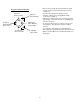
Remote Operator Control Panel (ROCP) - It is the same as a Local Operator Control Panel with the exception that it is not connected directly to the MMCP. It will communicate to the LOCP through a network connection of either dual Multi Mode fiber optic cable with SC connectors or an Ethernet (Cat5e or Cat6e) cable. Additional boxes can be added to control specific monitors if desired through this same method. Configuration is completed by following the procedure in this document.
Park – This operation will take the monitor through the following steps: • The Horizontal axis will move left in direction until it hits the hard stop (7°) and will remain there until the calibration time gets to zero it will then move right to the horizontal park position. (Range 7° to 354°) • The Vertical axis will move all the way up (0°) until it hits the hard stop and will remain until the calibration timer gets to zero.
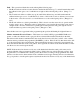
II SYSTEM CONFIGURATION INSTRUCTIONS • • • • • Each Dual OCP (Local or Remote) controls 2 monitors, one MicroLogix 1400 for each. Each Single OCP (Local or Remote) controls 1 monitor, one MicroLogix 1400. One OCP is wired to the MMCPs. This becomes the Local OCP (LOCP) and the other panel, connected by the network, becomes the Remote OCP (ROCP). To control the monitor from the Remote OCP the Monitor ID Number must match the Local OCP Monitor ID Number.
DUAL ALL COMPONETS OCP (LOCAL OR REMOTE) LAYOUT MicroLogix 1400 for Monitor #1 Manual Controls and Indicator Lights for Monitor #1 Terminal Blocks for Monitor #1 Manual Controls and Indicator Lights for Monitor #2 MicroLogix 1400 for Monitor #2 Terminal Blocks for Monitor #2 SINGLE OCP (LOCAL OR REMOTE) LAYOUT WITH ALL COMPONETS Manual Controls and Indicator Lights for Monitor Monitor - PLC Terminal Blocks for Monitor 8
• Before going through the setup instructions check that the connections between all boxes have been completed. • No data can be changed in display 1 and 2. • Displays 3 thru 6 are for setting Monitor Park position and oscillation. • Data can be changed at the cursor location by using the [UP] key to increase the value or [DOWN] key to decrease the value. • To enter the data and move to the next screen press the [OK] key. The data that is displayed will be entered.
WARNING!! While working inside the panel be aware of the terminals located at the bottom, they contain live electricity and caution should be exercised at all times.
III SETUP INSTRUCTIONS Important: Before continuing with the procedures below turn all Power On switches to the O position. This will allow for a smoother set up as the OCPs are configured. Failure to do this could cause problems with how the system operates. A. Set Up for LOCP (Local) or ROCP (Remote) operation. 1. Jumpers: All MMCP panels are wired with a set of jumpers in place that allow the Water Valve and Foam Valve or Auxiliary Device lights for the OCP to be tested for correct operation once built.
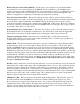
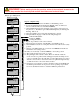
2.1. Locate the PLC inside the Control Panel enclosure. 2.2. Locate the user interface. [Up] Key Increase Value [Esc] Key Cancel Change ESC REMOTE ELKHART BRASS INDUSTRIAL EQUIP MODULAR-A4 [Right] Key Move Flashing Cursor Right OK [Left] Key Move Flashing Cursor Left [Down] Key Decrease Value [OK] Key Enter Value Fig. 2.2 – User Interface - Default Screen at Power Up 2.3. Press [OK] and the next screen will appear (Fig. 2.3). This is the monitor position data and will update as the monitor is moved.
3.2. To change the value use the diamond shaped buttons [UP] to increase or [DOWN] to decrease. Position range is 7 thru 354 in degrees, with 7 being full left. Keep in mind in order for the change to be made [OK] must be pressed, which will also move the program on to the next screen. Pressing [ESC] will cancel any changes and pressing it again will go to the beginning (Fig. 2.2). 3.3. The next screen that will appear is the Vertical Park Angle position (Fig.3.2).
4.1. Changing the Monitor ID number – Each ROCP and LOCP needs to be paired up as a duet system if in a networked configuration. This is not accomplished by the IP addressing but is completed by a Monitor ID number that the two share in common. The procedure to change this number is as follows: 4.2. Once in the user defined area press the [DOWN] arrow key until the screen appears that the Monitor ID value will be entered (Fig. 4.1). RUN ENTER MONITOR ID NUMBER = 1 Fig. 4.
RUN IP CONFLICT MAC ADDRESS = 0000ADFNC001 1 Fig. 6.1 – IP Conflict Error Screen 6.1. Cursor to the screen using the [UP] or [DOWN] arrow keys until the following screen appears (Fig. 6.2). The cursor will flash on the first digit of the last number. The only value that needs to be changed is the last two digits that appear on the screen. RUN CHANGE IP ADDRESS 192.168.032.010 = 010 010 Fig. 6.2 – Change IP Address Valid system IP addresses are as follows: 192.168.032.010 192.168.032.014 192.168.032.
B. Set Up for a ROCP 1. Monitor ID Number: The set up for the ROCP is the same as the LOCP and the same steps that were described above need to be followed. The one exception is in step III.A.5.1 that determines if the PLC is wired to the MMCP. This data needs to be a zero (0) as it will not be wired to a MMCP. 2. Setting the ROCP IP Address: Set the IP address to a unique one that has not been used. It is recommended to document the IP addresses that have been used to avoid future confusion. 3.
3. Auxiliary Input 3 – Will open all Foam Valves or Auxiliary Devices for the monitors included in the specific network. To activate this function wire a normally opened pushbutton between terminal block 75 and 24VDC for the original OCP Revision and to terminal 51 (or 51A) when using the internal 24VDC from the panel on later Revisions. 4. Auxiliary Input 4 – Will signal all monitors included in the specific network to perform the Park function.
IV SPECIFICATIONS General Specs • Input Power • • Electrical Load Panel Dimensions • Panel Weights • Operating Temperature Range 120/240 VAC (50/60Hz.) 1 Phase Power converts to 24 240 VA max. power VDC in control panel 2 AMPS MAX 24” x 36” (610mm x 914mm) – 2 Monitor OCP 20” x 24” (508mm x 610mm) – 1 Monitor OCP Approx. 100 lbs. (45 kg) – 2 Monitor OCP Approx. 80 lbs.
VI TROUBLESHOOTING OCP SYSTEM Symptom ROCP not controlling the correct or any monitor. • • • LOCP not controlling the correct or any monitor • • • • LCD screen Flashing IP CONFLICT MAC ADDR = ########## Unable to see the User Display Menu to make program changes.
Monitor physical position does not agree with the Position Data on the LCD • When running in a 50 Hz location the first line of the LCD display should look like this: ELKHART BRASS * • A 60 Hz location it should look like this: ELKHART BRASS Refer to Section III-D to change from one to the other. Warning: Do not attempt to disconnect or work on any electrical equipment in this system unless power is removed or the area is known to be non-hazardous.
At the ROCP with water flowing out of the nozzle and the Water Valve Opened light is not on At the ROCP with foam flowing out of the nozzle and the Foam Valve Opened or Auxiliary Device ON light is not on At the LOCP with a monitor oscillating the indicator light is not on At the ROCP with a monitor oscillating the indicator light is not on Park Light continually flashes quickly • Check for a burned out bulb • Check that the networked LOCP water valve open light is on • Check that the jumper is in place
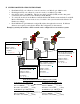
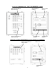
VII MOUNTING DIMENSIONS – Do Not Scale Drawings Figure 5: 2 Monitor OCP Mounting Dimensions Figure 6: 1 Monitor OCP Mounting Dimensions 22
NOTES:__________________________________________________________________________________ __________________________________________________________________________________________ __________________________________________________________________________________________ __________________________________________________________________________________________ __________________________________________________________________________________________ ___________________________________________________________
VIII ENGINEERING CHANGE REVISION EXPLANATIONS Revision A – ECN 110616 • Table of Contents o Added Engineering Revision Explanations section. • Section I o Added more detail on fiber connections under the Remote Operator Control Panel definition. • Section III - A o Added more detail pertaining to the jumpers in the MMCP and the problems that can occur. • Section III – D o When using the internal power of the panel, connect between the aux. input and terminal 51.
Revision D – ECN 131017 • Section VII o Added Park light indicator troubleshooting Revision E – ECN 140727 • Section I o Revised overview comments • Section III o Corrected Monitor Position LCD screen o Added Auxiliary and Foam function notes 25