
User guide

7
II SYSTEM CONFIGURATION INSTRUCTIONS
• Each Dual OCP (Local or Remote) controls 2 monitors, one MicroLogix 1400 for each.
• Each Single OCP (Local or Remote) controls 1 monitor, one MicroLogix 1400.
• One OCP is wired to the MMCPs. This becomes the Local OCP (LOCP) and the other panel,
connected by the network, becomes the Remote OCP (ROCP).
• To control the monitor from the Remote OCP the Monitor ID Number must match the Local OCP
Monitor ID Number. If more monitors are to be added to the system increment the Monitor ID
Number accordingly.
• Each OCP MicroLogix 1400 needs a unique IP Address throughout the network. If different
addresses are required consult Section III.A.6, IP Configuration, in this manual.
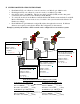
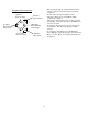
Example system layout and how a PLC network can be configured for a two monitor system:
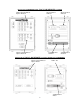
Network Parameter Worksheet (fill in for your system)
LOCP MicroLogix 1400 (left) #1 ROCP MicroLogix 1400 (left) #1
Monitor ID Number ____ (1-99) Monitor ID Number ____ (1-99)
Wired to MMCP? ____ (1 = YES) Wired to MMCP? ____ (1 = Yes)
IP Address 192.168.032.____ (10-25) IP Address 192.168.032.____ (10-25)
LOCP MicroLogix 1400 (right) #2 ROCP MicroLogix 1400 (right) #2
Monitor ID Number ____ (1-99) Monitor ID Number ____ (1-99)
Wired to MMCP? ____ (1 = Yes) Wired to MMCP? ____ (1=Yes)
IP Address 192.168.032.____ (10-25) IP Address 192.168.032.____ (10-25)
ROCP
MMCP
PLC #1
MMCP
PLC #2
LOCP
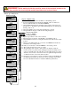
ROCP MicroLogix 1400 (left) # 1
MONITOR ID NUMBER = 1
WIRED TO MMCP?
ENTER 1 FOR YES = 0
IP ADDRESS
192 . 168. 032 . 012
LOCP MicroLogix 1400 (left) # 1
BELOW ARE THE OCP MicroLogix
1400 #1 DEFAULT SETTINGS
MONITOR ID NUMBER = 1
WIRED TO MMCP?
ENTER 1 FOR YES = 1
IP ADDRESS
192 . 168. 032 . 010
LOCP MicroLogix 1400 (right) # 2
BELOW ARE THE OCP MicroLogix
1400 #2 DEFAULT SETTINGS
MONITOR ID NUMBER = 2
WIRED TO MMCP?
ENTER 1 FOR YES = 1
IP ADDRESS
192 . 168. 032 . 011
ROCP MicroLogix 1400 (right) # 2
MONITOR ID NUMBER = 2
WIRED TO MMCP?
ENTER 1 FOR YES = 0
IP ADDRESS
192 . 168 . 032 . 013
MONITOR #1
MONITOR #2