
Technical data


14
CU3-01M CU3-02M
CU3-01M 8595188132220
CU3-02M 8595188132398
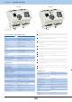
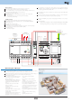
Central unit CU3-01M, CU3-02M
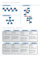
Central units CU3-01M and CU3-02M are the brain of the iNELS system, a "mediator“
between user‘s programming environment and controllers, units and actuators connected
to the bus.
It‘s possible to directly connect up to 2 lines of CIB buses in to CU3-01M and CU3-02M, and
on each bus we can connect up to 32 iNELS3 units.
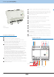
The main diff erence between CU3-02M and CU3-01M is that CU3-02M is moreover
equipped by RF module which enables communication with selected units from iNELS
RF Control system.
Central units CU-01M(02M) support also peripheral units from iNELS2 thanks to external
master MI3-02M/iNELS2.
User´s project and retentive data are stored in a non-volatile internal memory hereby data
are backed up without the supply voltage. Real time clock (RTC) backup for 10 days.
Power supply controlling system - network voltage and the status of the backup battery.
Possibility of setting time synchronization via NTP server.
The RJ45 Ethernet port‘s connector is located on the front panel of the unit, the transmission
speed is 100 Mbps.
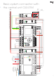
For CU3-01M (02M) it is possible to use 4 potential-free inputs for connecting external
controllers (buttons, switches, sensors, detectors, etc.) and 2 analog inputs 0-30V.
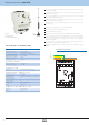
CU3-01M (02M) comes with OLED display that shows the current status and confi guration
of CU3-01M (02M) central unit.
CU3-01M (02M) can be controlled using the directional buttons on the front panel.
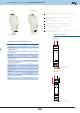
CU3-01M (02M) in 6-MODULE are designed for mounting into a switchboard on the
EN60715 DIN rail.
TECHNICAL PARAMETERS
EAN code
4x NO or NC to GND (-)
2 analogue inputs 0÷30
see separate datasheets
relay output- NC/GND only for EZS
max. 64 (2x32)
up to 576 units
(CU3-01M(02M) and 8x MI3-02M)
max. 32 units to one CIB line
max. 550m (depends on power loss)
max. 500 m
up to 8 (regards to increasing the cycle turns)
max. 10 m
RJ45 on the front panel
100 Mbps
green - Ethernet communication
yellow - Ethernet speed 100 Mbps
192.168.1.1
the set-up IP address can be displayed on the screen
INPUTS
Inputs:
Expandable with modules:
OUTPUTS
Output:
Number of connected units:
(directly to the CU3-01M(02M):
Expansion possibilities
external bus master:
COMMUNICATION
CIB
Maximum number of units:
Maximum cable length:
System bus EBM
Maximum cable length:
Number of connected ext. masters:
RS232 bus communication
Maximum cable length:
Ethernet
Connector:
Communication speed:
Indication of the Ethernet:
The default IP address:
green LED RUN - indicating the operating status of the unit
red LED ERR - indicating major errors
displays the current status and settings
color OLED
128x128 / 1:1 aspect ratio
26x26 mm
with a routing buttons
accuracy: 1s/day at 23 °C
CU301M, CU202M
LED indication:
OLED display:
Type:
Resolution:
Visible area:
Controlling:
The internal real-time clock:
22-30 V DC
27 V DC (from PS3-100/iNELS power supply)
110mA (at 27V DC)
-20 to +55 °C
-25 to +70 °C
max. 80%
IP 20 devices, IP 40 with cover in the switchboard
II.
2
any
to the switching board on the EN60715 DIN rail
6-MODULE
max. 2.5 mm
2
90 x 105 x 65 mm
250 g
POWER SUPPLY
Supply voltage:
Ideal supply voltage:
Rated current:
OPERATING CONDITIONS
Working temperature:
Storage temperature:
Humidity:
Degree of protection:
Overvoltage category:
Degree of pollution:
Operating position:
installation:
Design:
Terminal:
DIMENSIONS AND WEIGHT
Dimensions:
Weights:
RF CONTROL INTERFACE FOR CU302M
Communication protocol:
transmitting frequency:
Signal transmission methods:
Output for RF antenna:
RF antenna:
Free space range:
Oasis & RF Touch Compatible
868 MHz
bidirectionally addressed message
SMA connector
1 dB (part of package)
Up to 100 m