
Technical data
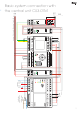


15
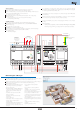
RS232
12V EZS
24 V baterie
Pomocné relé
cívka 230 V AC/5 mA
spínací kontakt
např. VS116K
baterie 1
12 V
baterie 2
12 V
+
-
+
-
O
VERL
O
AD
U LOW
OU
T
O
K
OUT
U
max. 32 jednote
+
-
+
-
CIB1
CIB2
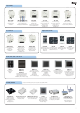
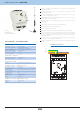
iNELS Designer & Manager
The confi gurations of units and the whole system are done via Ethernet, through
confi guration software - INELS Designer and Manager (hereinafter IDM), which is designed
for operating system MS Windows XP, W7, W8.
CU3-01(02M) can be remotely confi gured and controlled through external VPN (Virtual
Private Network).
Thanks to webserver integrated in CU3-01M(02M) it is possible to control remotely the
user´s functions through internet browser (PC, smartphone, tablet).
Through CU3-01M(02M), it is possible to remotely upgrade fi rmware on the connected
bus units.
Supported Software:
- P
arameterization, confi guration, control and visualization: iNELS Designer & Manager (IDM).
- Promoting free programming according to IEC 61131-3 standard (in preparation).
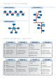
iNELS Designer & Manager (IDM) is a programming environment, which is designed for creating
projects for iNELS BUS System‘s installations with the CU3-01M(02M) central unit.
IDM allows management to address the requirements of lighting, blinds or shutters, heating, air
conditioning to the overall supervision of the installation and alarm reporting.
IDM provides the following:
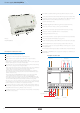
24 V battery
battery 1
12 V
battery 2
12 V
CIB Bus installation:
Two-wired bus with an arbitrary topology (not only to be as closed circle).
With its own modulated communications on the DC voltage supply.
One line of CIB bus allows you to connect up max. 32 units of iNELS3, or iNELS2 if you use
external master MI3-02M/iNELS2 with a current load max. 1A.
The current load of one line is max. 1A.
Maximum length of the bus is approximately 550 m (depends on the voltage drop).
Recommended cable :
- twisted shielded pair of cross sectional area 0.8 mm
2
for example:
J-Y(ST)Y 2x2x0.8, YCYM 2x2x0.8.
The EBM System Bus:
Used to connect the CU3-01M(02M) central unit with MI3-02M external masters,
MI3-02M/iNELS2, GSM communicator GSM3-01M or converter DALI/DMX EMDC-64M.
Strictly linear topology.
Max. length of the line of bus is 500m.
The EBM bus has to be terminated at both ends.
This part adapted to be inserted between terminals is included into central units packages
and it is necessary to insert between terminals EBM+ and EBM-.
Reccomended cabling:
- UTP CAT5e and higher.
EBM to MI3-02M, MI3-02M/iNELS2,
GSM3-01M or EMDC-64M
Auxiliary relay
coil 230V AC/5 mA
switching contact
e.g. VS116K
- the possibility of automatic numbering project
- easy-shifting of units for superior masters
- fi ltering units by name
- f
iltering units by type (switching, dimming, etc.)
- sorting units in the list according to their
defi nitions (type, hardware address, unit
name ...)
- visualization of the bus in terms of HW
addresses‘s number
- visualization of the bus in terms of the
current load
- creating of the fl oors
- creating layers in these levels (up to 5 layers)
- visibility settings / invisibility of the
individual layers
-
assignment of the fl oor plan or only the base color
- possibility to zoom in on the fl oor plan
- the number of units on the web server is not
restricted
- the possibility of entering multiple
conditions
- the possibility of comparing diff erent
variables
- visualization of the connections between
the elements or element groups
- the possibility of adding custom chart icons
- the possibility of simulation functions
- comprehensive list of individual connections
- the possibility of breaking down elements
into logical groups
- the possibility of using timers and counters
- transparent management of users and their
roles
- create an unlimited number of heating
programs
- signalizing the status of units