
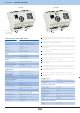
Technical data


16
+
+
+
-
-
-
-
OUT
PS3-100/iNELS 8595188131568
+
85 – 253 V AC
27 V iNELS
OVERLOAD
U
OUT
LOW
U
OUT
OK
+12V OK
CHARGE
U
PRI
FAIL
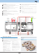
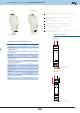
Power supply PS3-100/iNELS
PS3100/iNELS is a stabilized switching power supply, with the total power of 100 W.
Used to supply central units and external master within intelligent electro-installation iNELS.
Through bus separators from the supply voltage BPS3-01M and BPS3-02M, it supplies
supplies CIB bus lines from which iNELS peripheral units are also powered.
Used in the instrumentation fi eld.
Fixed output voltage DC 27,6 V and DC 12,2 V, galvanically isolated from the mains.
Power source of 27 V and 12 V have a common ground terminal GND.
Electronic short circuit protection, high-capacity and thermal overload, over voltage.
UPS functions - backup of output 24V and 12V on connected batteries.
Recharging the batteries from 27 V source.
Protection battery backup fuse - protection against short circuit and reverse polarity battery.
Continuously adjustable maximum battery charging current.
Indication of operating and fault conditions 6 LED diodes on the front panel of the power supply.
2 STATUS outputs with open collector for reporting operational status of the source.
Source supplies power to the priority system iNELS, the remaining power is used for
rechargeable batteries.
When the battery is fully discharged, the battery is automatically disconnected from the load.
PS3-100/iNELS in 6-MODULE version is designed for mounting into a switchboard, on
DIN rail EN60715.
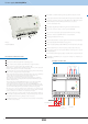
The device consists of several functional blocks.
The basic part is 100 W power supply with 2 output voltage levels.
Voltage of 27.6 V is used to supply the system iNELS and to recharge the batteries.
Voltage of 12.2 V is for power as intrusion detectors (PZTS) or EPS.
Both voltages are available without interruption during power AC power supply (UPS
function) - assuming they are connected to a backup battery.
Other parts of the source circuits are battery backup and recharge, which provide switching
mode connection, charging and disconnecting the battery.
- When in the backup mode, the battery is completely discharged, the circuit is immediately
switched off to avoid deep discharge. The maximum discharge current is also
guarded - when exceeded, the batteries are again disconnected.
- If the switched source is working (oscillating), and its output voltage are greater than
26.9 V, the backup batters are charged by the current, and the maximum value is set by
trimmer on the panel source.
- When charging the yellow LED CHARGE illuminates. The source fi rst feeds the iNELS
system, and the remaining capacity of up to 100 W only recharges the battery.
- If the output is high, this disconnects the charge (the yellow LED CHARGE switches off ).
- Upon further increasing, the load further decreases the voltage source and the load current
also fl ows from the battery (power supply and battery power to the load together).
Note: If the source is disconnected from the AC network (does not oscillate), and you
connect batteries now, the batters remain disconnected and power outputs are without
power. To activate, the source must be connected to the power supply.
The last part of the unit are signaling circuits and status outputs. STATUS outputs (see
technical data) are equipped with current limiting, so they can switch signaling components
directly without external resistors (e.g. LED, optocouplers or relay coil).
The LED signaling function is given in the table of technical parameters and illustratively
described in seven case studies.
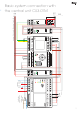
24 V battery
battery 1
12 V
battery 2
12 V
external DC source
EAN code
Example of connection
Description of device functions
12 V
security sensors