
Technical data


18
MI3-02M 8595188132411
MI3-02M/iNELS2 8595188150637
+
-
+
-
CIB1
CIB2
+ 27V
EBM -
EBM +
GND
BPS3-02M
MI3-02M
EBM+ EBM- GND
7
7
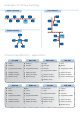
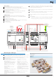
External master bus CIB MI3-02M
External master MI3-02M provides expansion of the amount of units iNELS3 connected to the
central unit CU3-01M or CU3-02M for 2 times 32 units.
If you require the use of a central unit CU3-01 (02M) in combination with the iNELS2 units ,
all the units must be connected to the bus CIB lines, which are based on an external master
MI3-02M/iNELS2.
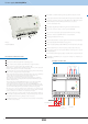
Up to 8 modules MI3-02M or MI3-02M/iNELS2 can connect to a central unit via the system
bus EBM.
In conjunction with the central unit CU3-01M(02M), it can achieve a maximum capacity of the
bus iNELS of up to 576 units.
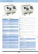
MI3-02M and MI3-02M/iNELS2 have marked on the front panel of the unique hardware
address. This address belongs to the line CIB1. IDM software then automatically sets the
hardware address of the BUS line CIB2 (this address is always one value higher).
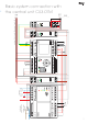
MI3 units are supplied from PS3-100/iNELS.
To power the lines CIB, it is necessary to use a BUS separator BPS3-02M or BPS3-01M (supply
only one line). In case of using MI3-02M/iNELS2 is used BPS2-02M or BPS2-01M.
Status signaling of each bus (operation, fault) is indicated by two-color LEDs on the front
panel of the module.
The last MI2-02M connected to the EBM bus must be closed with a 120 Ω termination resistor.
This part adapted to be inserted between terminals is included into central units packages
and it is necessary to insert between terminals EBM+ and EBM-.
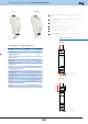
MI3- 02M, MI3-02M/iNELS2 in 1-MODULE version is designed for mounting into a switchboard,
on DIN rail EN60715.
max. 64 (2x32)
2 x CIB
EBM
green LED
red LED
max. 2x550 m
max. 500 m
Number of connected units:
Installation BUS:
Data BUS:
Unit status indication:
Bus fault indication:
Length of BUS CIB wire:
Length of BUS EBM wire:
OUTPUTS
TECHNICAL PARAMETERS
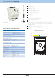
Example of connection
22-30 V DC
27 V DC
25 mA (at 27V DC)
-20 to +55 °C
-25 to +70 °C
max. 80 %
IP20 device, IP40 mounting in the switchboard
II.
2
any
in a switchboard on DIN rail EN 60715
1-MODULE
max. 2.5 mm
2
90 x 18 x 65 mm
80 g
POWER SUPPLY
Supply voltage:
Ideal supply voltage:
Rated current:
OPERATING CONDITIONS
Operating temperature:
Storage temperature:
Humidity:
Protection degree:
Overvoltage category:
Pollution degree:
Operating position:
Installation:
Design:
Terminal:
DIMENSIONS AND WEIGHT
Dimensions:
Weight:
COMMUNICATION
from PS3-100/iNELS
EAN code