
Technical data


30
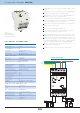
EMDC-64M
ERR EBM
N
DALI 64 DALI 1 DMX 1 DMX 32
L
N
-
+
EBM
EBM
120 Ω
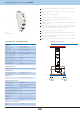
Converter iNELS - DALI/DMX EMDC-64M
Supply voltage:
Input interface:
Output interface:
Power supply:
Error:
Communication:
Operating temperature:
Storage temperature:
Protection degree:
Control device purpose:
Control device construction:
Characteristic of automatic action:
Heat and fi re resistance category:
Anti-shock category (immunity):
Rated impulse voltage:
Overvoltage category:
Pollution degree:
Operating position:
Installation:
Implementation:
Dimension:
Weight:
230 V AC
EBM bus (RS485 communication)
iNELS RF Control
DALI (max. 64 ballasts)
DMX (max. 32 receivers, with repeator to 64)
green LED RUN
red LED ERR
bicolour LED DALI/DMX
-20°C to +55°C
-30°C to +70°C
IP20 device, IP40 mounitg in the switchboard
operating control device
individual control device
1.B.E
FR-0
class 2
2.5 kV
II.
2
any
into switchboard on DIN rail EN60715
3-modulle
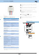
90 x 52 x 65 mm
130g
EAN code
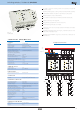
Unit EMDC-64M is designed to control electronic ballasts DALI and DMX receivers from
the iNELS.
EMDC-64M allows you to control up to 64 independent electronic ballasts DALI (Digital
Addressable Lighting Interface) for fl uorescent , LED and other lamps.
EMDC-64M allows the connection of up to 32 receivers DMX (Digital Multiplex) in one
segment. When using repeaters, it can control up to 64 devices.
Control is possible from the iNELS BUS System via the system bus EBM or from the RF
Control wireless transmitters. Selection of control (RF/EBM ) and controlled (DALI/DMX)
interface is done via DIP switches on the front panel of the unit.
When used in the context of bus wiring (interface EBM) it is set using the IDM software.
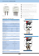
Unit EMDC - 64M is powered by 230 V AC.
DALI bus is powered directly through the unit EMDC - 64M.
In the event that this is the last unit on the system bus EBM, it is necessary to use a
termination resistor having a nominal resistance value of 120Ω .
DMX bus must be terminated at its end resistor with a nominal resistance value of
120Ω. Bus termination DMX -side EMDC - 64M is already implemented inside the unit.
Two members of the nominal resistance value of 120Ω adapted for easy insertion to the
terminals come with the package. To end the system bus EBM, a member is inserted
between the terminals EBM+ and EBM- on last unit on the bus. To end DMX bus termination
is performed on the terminals of the last receiver (slave unit) e.g. DCDA-33M/RGB.
PRG button and MINI USB connector on the front panel are used to set up
communication with the transmitter RF Control.
EMDC-64M in 3 module is designed for panel mounting on DIN rail EN60715.
Example of connection
OPERATING CONDITIONS
POWER SUPPLY
COMMUNICATION
INDICATION
DIMENSION AND WEIGHT
TECHNICAL PARAMETERS
RF CONTROL INTERFACE
Communication protocol:
Transmitting frequency:
Signal transmission method:
Output for RF antenna:
RF Antenna:
Range in free space:
Oasis & RF Touch Compatible
868 MHz
bidirectionally addressed message
SMA connector
1 dB (supplied)
up to 100m
EMDC-64M 8595188150309
External antenna AN-E: 859415759012
Internal antenna AN-I: 8595188161862