
Technical data


31
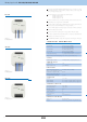
DCDA-33M/RGB 8595188146807
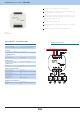
CIB+
CIB-
A
B
GND
120 Ω
12-24 V DC
GND
Supply terminals:
Supply voltage:
Consuption:
Supply voltage tolerance:
Dimming load:
Number of channels:
Rated current:
Output power:
Output voltage:
Switching voltage:
DALI:
CIB:
DMX:
Operating temperature:
Storage temperature:
Protection degree:
Overvoltage category:
Pollution degree:
Operating position:
Installation:
Implementation:
Dimension:
Weight:
Dimming actuator DCDA-33M/RGB
Un+, GND
12-24V DC stabilized
min. 0.8W max. 48W
+10 / -10%
LED 12-24V DC with common cathode /
RGB LED 12-24V DC with common cathode
3
0 - 2A
3 x 40W
0 - 50V
Un
1200bit/s, 250 mA
compatible with iNELS3, consumption < 2mA
250 kbit/s, 512 CH
-20°C to +55°C
-30°C to +70°C
IP20 device, IP40 mounitg in the switchboard
II.
2
any
into switchboard on DIN rail EN60715
3-modulle
90 x 52 x 65 mm
135g
POWER SUPPLY
OPERATING CONDITIONS
OUTPUTS
CONTROL
DIMENSION AND WEIGHT
Setting the DALI communication interface - Switch 1 and 2.
Setting address - Switch 5-10.
Setting the CIB communication interface - Switch 1 and 2.
Address is not settable, is given HW address.
Setting the DMX communication interface - Switch 1.
Setting address - Switch 2-10.
Setting the DIP switches
DCDA-33M/RGB dimming actuator is designed for dimming RGB and LED light sources
with power supply 12-24 V DC, which are controlled by variable current.
The actuator has three independent channels and each output channel is individually
addressable and controllable.
If desired, the channels can be associated as a single actuator for actuating the RGB
source.
DCDA-33M/RGB actuator can be controlled from the bus DALI, DMX or CIB .
DCDA-33M/RGB can directly control from the system iNELS where the communication
interface is the installation CIB.
If ithe communication interface DALI or DMX is used, the DALI master EMDC-64M can
be used.
Setting the communication interface and addresses of actuators is performed using DIP
switches:
a) switch No. 1
- In the upper position determines DALI or CIB
- In the lower position determines DMX
b ) switch No. 2 (if that switch 1 is in the upper position)
- In the upper position determines DALI
- In the lower position determines CIB
Using the control buttons on the front panel, you can manually control the output.
The input circuits of communication interfaces are optically isolated from the supply
voltage connected lamp unit, and is therefore resistant to electromagnetic interference.
DCDA-33M/RGB in 3-module is designed for panel mounting on DIN rail EN60715.
EAN code
Example of connection
TECHNICAL PARAMETERS
DALI bus
DMX bus