M:\Product Information\366-348\Instructions\366-348 MGB Fuel Injection Installation Instructions_Grant_2.doc 366-348 Fuel Injection Conversion Installation Instructions 1975-1980 MGB with a Zenith Stromberg Carburetor CARB E.O. Number D-453-4 (75-79) Introduction The US Spec MGBs built from 1975 on were designed around the emissions standards adopted by the United States.
M:\Product Information\366-348\Instructions\366-348 MGB Fuel Injection Installation Instructions_Grant_2.
M:\Product Information\366-348\Instructions\366-348 MGB Fuel Injection Installation Instructions_Grant_2.doc Installation Part 1 – Prepare the Vehicle, Drain Fluids 1. 2. 3. 4. Disconnect the battery ground cable. You will need a solid, level surface to work on. Jack up the rear end of the car and support is securely on two jack stands. Drain the fuel tank. The safest method is to use a fuel siphon pump to transfer the fuel into a proper gasoline storage container.
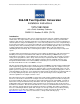
M:\Product Information\366-348\Instructions\366-348 MGB Fuel Injection Installation Instructions_Grant_2.doc 2.3 11. Locate the water choke on the ZS Carb (2.2). 2.2 12. Loosen the hose clamp and disconnect the coolant hose that runs from the water choke (2.3) to the water choke outlet at the back of the cylinder head. 13. Loosen the hose clamp and disconnect the coolant hose that runs from the water choke (2.4) to the steel coolant line (2.6) that runs next to the exhaust manifold. 14.
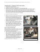
M:\Product Information\366-348\Instructions\366-348 MGB Fuel Injection Installation Instructions_Grant_2.doc 18. Locate the hose (6.1, 6.2) that runs from the carb to the crankcase vent pipe (6.3) on the front of the engine. 19. Loosen the hose clamp at the carb and disconnect the hose. 6.1 6.2 366-348_Instructions_Fig 6 20. Loosen the hose clamp at the crankcase vent pipe (6.3) and remove the hose. This hose will be replaced by a new hose supplied in the kit. 6.3 366-348_Instructions_Fig 6B 21.
M:\Product Information\366-348\Instructions\366-348 MGB Fuel Injection Installation Instructions_Grant_2.doc 24. On the back of the carb, locate the throttle cable (9.1) and the bellcrank (9.2) 25. Disconnect the throttle cable (9.1) and let it hang loose as shown in Fig 9. The throttle cable is secured to a bracket on the heat shield and that will be removed shortly. 9.2 9.1 366-348 Inst Fig 9 26. Remove the four nuts that secure the carb to the intake manifold.
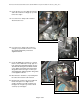
M:\Product Information\366-348\Instructions\366-348 MGB Fuel Injection Installation Instructions_Grant_2.doc 34. Locate the nut (11.3) securing the heat shield bracket (11.4) to the stud (11.5) on the heater return pipe. Remove the nut and save it-we will need it later. 35. Remove the heat shield bracket (11.4) and the heat shield (11.6) by pulling it up and off the 4 carburetor studs and the stud (11.5) on the water pipe. Set it aside. 11.3 11.4 11.5 11.6 36.
M:\Product Information\366-348\Instructions\366-348 MGB Fuel Injection Installation Instructions_Grant_2.doc Installation Part 3-Modification of the Heat Shield The heat shield will be modified and reinstalled with the fuel injection throttle body. Although it is possible run a car with the fuel injection system installed without the heat shield, the under-hood temperature will be quite high, and we strongly recommend against it. 41. Remove the two Phillips head screws (14.
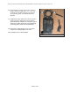
M:\Product Information\366-348\Instructions\366-348 MGB Fuel Injection Installation Instructions_Grant_2.doc 46. Cut the bracket to remove the 3.5” long section of the lip or flange from both sides (17.1, 17.2). You can make the cuts with a hacksaw. You can also use a grinder, jig saw, or a Sawzall instead of a hacksaw. 17.1 47. Lightly file the edges where both cuts were made to remove any burrs. At this point you may want to repaint the bracket.
M:\Product Information\366-348\Instructions\366-348 MGB Fuel Injection Installation Instructions_Grant_2.doc 18.1 Installation Part 4 - Fitting the Throttle Body 49. Pick up the throttle body. Note that one of the four mounting bolts has already been installed, and the throttle stop was installed afterward. This effectively traps the bolt. NOTE: The throttle stop has been preset and the Electronic Control Unit (ECU) has been calibrated using this throttle stop.
M:\Product Information\366-348\Instructions\366-348 MGB Fuel Injection Installation Instructions_Grant_2.doc 58. Hang the modified heat shield assembly in position, (with the gasket toward the manifold) using the stud on the water pipe to support the heat shield. The four bolt holes in the heat shield should line up with the four holes in the manifold. Replace the nut on the stud on the water pipe loosely- we just want to keep the heat shield assembly in position. 59.
M:\Product Information\366-348\Instructions\366-348 MGB Fuel Injection Installation Instructions_Grant_2.doc Installation Part 5 - Laying the Harness in Place The brain of the fuel injection system is the Electronic Control Unit, or ECU. This will live in the cockpit.
M:\Product Information\366-348\Instructions\366-348 MGB Fuel Injection Installation Instructions_Grant_2.doc 70. Locate the branch of the harness that has the relay (25.1) and the inline fuse holders (25.2), and route it over to the right hand side of the engine compartment. Although missing in this particular picture, we encourage the use of fender covers or towels to protect the paint. 25.2 71.
M:\Product Information\366-348\Instructions\366-348 MGB Fuel Injection Installation Instructions_Grant_2.doc Installation Part 6 - Connecting the Harness to the Throttle Body 73. Locate the connector on the harness for the Idle Air Control Motor and plug it in. (26.1) 366-348 Inst Fig 26B 366-348 Inst Fig 26C 74. Locate the connector on the harness for the Fuel Injector and plug it in. (26.2) 26.1 26.1 75. Locate the connector on the harness for the Throttle Position Sensor (TPS) and plug it in. (26.
M:\Product Information\366-348\Instructions\366-348 MGB Fuel Injection Installation Instructions_Grant_2.doc Installation Part 7 – Installing the Manifold Absolute Pressure (MAP) Sensor The MAP sensor is a variable resistor used to monitor the difference between the pressure inside the intake manifold and normal atmospheric pressure outside the manifold. This information is used by the electronic Control Unit (ECU) to determine engine load.
M:\Product Information\366-348\Instructions\366-348 MGB Fuel Injection Installation Instructions_Grant_2.doc Installation Part 8 - Engine Coolant Temperature (ECT) Sensor 85. Locate the factory water choke outlet at the left rear corner of the cylinder head. When cars are converted to a manual choke, this outlet is sometimes removed. If yours is missing, you will need a Moss #470-245 water choke outlet because engine coolant must flow past the ECT in order for it to work properly. 86.
M:\Product Information\366-348\Instructions\366-348 MGB Fuel Injection Installation Instructions_Grant_2.doc 92. Locate the two 1/4-28 x 2” studs supplied in the kit. 93. Apply thread sealant (Permatex 54540 or equivalent) to the last ¼ inch of each stud. (Fig 37) 94. Thread the ends of the studs with sealant into the holes at the back of the head. (Fig 38) 366-348 Inst Fig 37 366-348 Inst Fig 38 366-348 Inst Fig 39 366-348 Inst Fig 39B 95.
M:\Product Information\366-348\Instructions\366-348 MGB Fuel Injection Installation Instructions_Grant_2.doc 104. Find the fuel injection harness connector with the blue inner seal (47.1) Connect it to the to the ECT sensor. The clip on the connector (47.2) should snap into place. 47.2 47.1 366-348 Inst Fig 47 105. Locate the 22” long piece of 3/8” heater hose supplied in the kit (Moss #051-260).
M:\Product Information\366-348\Instructions\366-348 MGB Fuel Injection Installation Instructions_Grant_2.doc Installation Part 9- Tapping into the Tachometer Wire 108. If you have a “Federal” MGB (built for sale outside California) you should have a cylindrical barrel-type coil (60.1). Locate the two white w/black stripe wires attached to the negative side of the coil (60.2). Look at the coil; the negative side of the coil should be marked with a “-“.
M:\Product Information\366-348\Instructions\366-348 MGB Fuel Injection Installation Instructions_Grant_2.doc Installation Part 10- Terminating & Connecting the Fuel Injection Harness 113. Organize the various electrical connectors supplied in the kit. 65.4 65.6 114. Find the two black wires that have inline fuses (65.1, 65.2). These are the fuel injection harness power leads. 115. Strip the ends and crimp one female spade connector (65.3) onto each of these two wires.
M:\Product Information\366-348\Instructions\366-348 MGB Fuel Injection Installation Instructions_Grant_2.doc 122. The fuse block (68.1) is secured to the right inner fenderwell. Look at the side of the fuse block closest to the front of the car. Locate the two brown wires with female spade connectors (68.2, 68.3) connected side by side on the lowest pair of male spade terminals. These two male spade terminals are +12V Constant (powered all the time) and the position on the fuse box is labeled “7”.
M:\Product Information\366-348\Instructions\366-348 MGB Fuel Injection Installation Instructions_Grant_2.doc 130. There is another pair of male spade terminals on the fuse block immediately above the wires you just connected. This position is labeled “5”. While the outermost spade (74.1) is available on some MGBs, and we know that it is used on the 80 MGB. This means that the piggyback procedure we just went through (see above) may have to be repeated on your car.
M:\Product Information\366-348\Instructions\366-348 MGB Fuel Injection Installation Instructions_Grant_2.doc Installation Part 11- Connecting the Throttle Cable 139. Route the throttle cable over the harness and over the vacuum line for the brake booster. 366-348 Inst Fig 80 140. Push the cylindrical end (82.1) at the tip of the throttle cable into the hole in the throttle cable bellcrank. You will need to guide the cable through the slot (82.1) and into the V-channel (82.3) of the bellcrank arm.
M:\Product Information\366-348\Instructions\366-348 MGB Fuel Injection Installation Instructions_Grant_2.doc 142. Pull up on the cable (83.1) while rotating the bellcrank (83.2) to open the throttle. This will provide enough slack to slide the cable through the slot in the bracket. 143. Slide the cable (85.1) through the slot in the bracket (85.2), then lower the threaded end of the throttle cable housing (85.3) down through the hole in the bracket as you release the tension on the throttle cable. 83.
M:\Product Information\366-348\Instructions\366-348 MGB Fuel Injection Installation Instructions_Grant_2.doc 92.5 Part 12 continued 152. Slide a small hose clamp on each end of the 32” piece of 5/16” fuel hose included in the kit. A small amount of petroleum jelly will make it easier to push the hose onto the nipples. 92.4 92.3 153. Push the hose onto the “IN” nipple (91.1) on the throttle body. 91.1 154. Run the hose in an arc (92.1, 92.2, and 92.3) and push the hose onto the fuel filter nipple.
M:\Product Information\366-348\Instructions\366-348 MGB Fuel Injection Installation Instructions_Grant_2.doc Installation Part 14- Vacuum Connection, MAP Sensor to Throttle Body 160. Find the 30” length of 5/32” vacuum hose supplied in the kit. 161. Form it into a loop 3” in diameter at one end with 6” of hose (97.1) beyond the loop. 162. Use two zip ties (97.2) to secure the loop. 97.2 97.1 3” We are going to install this so that the loop (97.3) is the lowest section of the hose. 97.1 97.
M:\Product Information\366-348\Instructions\366-348 MGB Fuel Injection Installation Instructions_Grant_2.doc Installation Part 15- Air Intake & Filter 168. Find the air intake, air filter, and the SAE40 bandtype hose clamp for the air filter provided in the kit. The manufacturer has discontinued the orange air filter; the filter in the kit will be blue or black. 169. Slide the 2.5” conical air filter and a SAE 40 hose clamp onto the air intake housing.
M:\Product Information\366-348\Instructions\366-348 MGB Fuel Injection Installation Instructions_Grant_2.doc 175. Find the three 2 3/8” long Allen head bolts for the air intake housing and the packet of blue Loctite, all of which are supplied in the kit. 176. Test fit all the mounting bolts in the throttle body before opening the Loctite. Start with the lower rear bolt (110.1).
M:\Product Information\366-348\Instructions\366-348 MGB Fuel Injection Installation Instructions_Grant_2.doc Installation Part 16 - Fuel Return Hose 120.1 Fuel injection systems use a high pressure fuel pump, which maintains pressure at the injector. To do so, fuel is constantly circulating from the tank to the throttle body and back again. We are going to install the fuel return line. 184. Find the OUT nipple (120.1) on the throttle body. It is toward the rear of the throttle body, and it points up.
M:\Product Information\366-348\Instructions\366-348 MGB Fuel Injection Installation Instructions_Grant_2.doc 194. In the right footwell: pull the two red wires into the cockpit and route them behind the dash and over to the driver’s side of the car. 195. Locate the Fuel pump Inertia switch (Fig 122B) up under the dash on the driver’s side. The switch has two male spade terminals.
M:\Product Information\366-348\Instructions\366-348 MGB Fuel Injection Installation Instructions_Grant_2.doc Installation Part 17 – Removing the Stock Fuel Pump For this part if the installation, the car needs to be jacked up and supported on proper automotive jack stands on a solid, level surface. You will be working underneath the car and the car must be stable. 200. Remove everything that is loose from the trunk. 128.3 128.4 201.
M:\Product Information\366-348\Instructions\366-348 MGB Fuel Injection Installation Instructions_Grant_2.doc Installation Part 18 – Fuel Return Hose & Pump Power Wire 210. In the right rear corner of the trunk, directly below the right reverse lamp assembly (130.1), there is a white plastic plug in the floor of the trunk. (130.2) 130.1 211. Using a flat bladed screwdriver, gently pry the plug out. Set it aside- we are going to use it later.
M:\Product Information\366-348\Instructions\366-348 MGB Fuel Injection Installation Instructions_Grant_2.doc Part 18, continued 217. Replace the plastic plug/grommet in the hole in the trunk floor and push the hose through the hole in the plug and into the trunk. (Fig 138) 366-348 Inst Fig 138 218. From inside the trunk, pull the hose until you have taken up most of the slack. (figure 139) 219.
M:\Product Information\366-348\Instructions\366-348 MGB Fuel Injection Installation Instructions_Grant_2.doc Part 19, continued 222. Slide small hose clamps over each end of the 24” length of 5/16” fuel hose. 223. Remove the original hose from the steel fuel line over the rear axle. 166.2 224. Connect one end of the 24” piece of hose to the original steel fuel line. Tighten the clamp.
M:\Product Information\366-348\Instructions\366-348 MGB Fuel Injection Installation Instructions_Grant_2.doc Part 19, continued 232. Strip the insulation off the end of the red wire with white stripe. 176.1 176.3 233. Crimp the #8 ring terminal (supplied in the kit) onto the wire. Secure it to the positive terminal on the fuel pump, which is labeled “+”. (176.1) 234. Find the 30” long piece of black wire, a ¼” ring terminal and a #8 ring terminal supplied in the kit. 176.2 235.
M:\Product Information\366-348\Instructions\366-348 MGB Fuel Injection Installation Instructions_Grant_2.doc Installation Part 20 – Mounting the High Pressure Fuel Pump 238. Find the foam sleeve, large “P” clamp, the 1/4-28 x 3/4" bolt, and the 1/4" lock washer supplied in the kit. Slice the foam sleeve lengthwise. (Fig 178) We are going to wrap the foam around the pump to cut down on the noise.
M:\Product Information\366-348\Instructions\366-348 MGB Fuel Injection Installation Instructions_Grant_2.doc Part 20, continued 183.2 243. Reach over the axle (183.1) and move the pump assembly towards the original fuel pump hole. Rotate the p-clamp around the pump until the bolt is pointed toward the welded nut (183.2) closest to the center of the vehicle. 183.1 366-348 Inst Fig 183 244. Once the pump is up against the bulkhead, you will not be able to see the bolt or the welded nut from underneath.
M:\Product Information\366-348\Instructions\366-348 MGB Fuel Injection Installation Instructions_Grant_2.doc Installation Part 21 – Connecting the Fuel return Hose in the Trunk In early 1978, the filler neck hose used on the late MGB went from a BHH1886, a sharply bent, nearly 90-degree hose (Fig 190) to a BHH206 hose that was not so sharply bent (Fig 192). In the early version, the section of hose from the filler cap was nearly horizontal (190.1).
M:\Product Information\366-348\Instructions\366-348 MGB Fuel Injection Installation Instructions_Grant_2.doc Installation Part 21.1 – Fuel Filler Neck, Early Hose (to early 1978) For cars with the later hose, go to Part 21.2 257. Slide one of the large band-type clamps over the cut end of the shortened early filler hose. (199.1) 258. Install the cut end of the hose over the top of the fuel return adapter and start the other end onto the fuel filler inlet pipe. (201.1) 199.1 201.
M:\Product Information\366-348\Instructions\366-348 MGB Fuel Injection Installation Instructions_Grant_2.doc Installation Part 22 – Installing the ECU You will be removing some items temporarily to facilitate the installation of the ECU system. Keep these items and their mounting hardware organized, as they will be reinstalled once the ECU is mounted. These images and instructions are specific for the 77-80 application, Earlier cars will differ. 267.
M:\Product Information\366-348\Instructions\366-348 MGB Fuel Injection Installation Instructions_Grant_2.doc Part 22, continued 274. From the passenger side footwell, remove the under-dash trim panel. 275. Using a 7/16 socket, remove the 2 nuts under the dash that secure the evaporative emissions canisters. (228.1) 228.1 366-348 Inst Fig 228 276. Pull up on the evaporative emissions canisters and place them on a block of wood (230.1) or rolled up magazine.
M:\Product Information\366-348\Instructions\366-348 MGB Fuel Injection Installation Instructions_Grant_2.doc Part 22, continued 281. Reinstall the carbon canisters, remembering to tighten the nuts inside the cockpit. Reinstall the windshield washer bottle bracket, replace the washer bottle lid, reconnect the wires for the washer pump, and reconnect the run-on control valve. (Fig 235) 366-348 Inst Fig 235 282. Back into the passenger’s side footwell. 236.1 283.
M:\Product Information\366-348\Instructions\366-348 MGB Fuel Injection Installation Instructions_Grant_2.doc Part 22, continued 289. Connect the two harness ECU plugs. One plug is wider than the other and has more pins, so you cannot mix them up. Push the plugs in until you hear /feel a click, indicating the locking tabs have engaged. (Fig 241) 290. Reinstall the under dash trim piece. It may need to be slightly trimmed to clear the ECU. 366-348 Inst Fig 241 291.
M:\Product Information\366-348\Instructions\366-348 MGB Fuel Injection Installation Instructions_Grant_2.doc Installation Part 23 – Testing the Fuel Injection Wiring & Plumbing 294. Reconnect the battery. 295. Turn the key to the on or run position (not to START). Listen for the fuel pump, which will run for about 3 seconds every time you turn the key on. If you do not start the car, the fuel pump will shut off automatically. 296.
M:\Product Information\366-348\Instructions\366-348 MGB Fuel Injection Installation Instructions_Grant_2.doc Installation Part 24 – Refilling to Cooling System 302. 248.1 248.2 Back in the engine bay. 303. Check the lower radiator hose clamp to make sure it has been retightened. We will now refill the cooling system. 304. Set heater control in the cockpit to HOT. 305. Remove the cap on the expansion tank. (248.1) 306.
M:\Product Information\366-348\Instructions\366-348 MGB Fuel Injection Installation Instructions_Grant_2.doc Installation Part 25 – Starting the Engine We are going to start the engine, which we need to do before we can top up the coolant. Before we turn the key, it is important to understand how the system works and what may happen when we try and start the engine. Every time you turn the key ON, a small amount of fuel is injected to help startup.
M:\Product Information\366-348\Instructions\366-348 MGB Fuel Injection Installation Instructions_Grant_2.doc Installation Part 26 – Tune Up & Maintenance California Air Resources Board Executive Order Number The CARB E.O. number for this kit is: D-453-4 IDLE SPEED Upon startup engine should rev up above 1200rpm and then over time drift down to ~950rpm depending on the temperature.
M:\Product Information\366-348\Instructions\366-348 MGB Fuel Injection Installation Instructions_Grant_2.doc Installation Part 27 – Troubleshooting Problem - Car will Not Start 1. Check Fuel Pump 1.1. Listen for operation of the fuel pump in the first 3 seconds after turning the ignition key to ON. Remember, the pump will shut off automatically if the key is left in the run position without going to the START position. 1.2. If the pump is operating, go to 3 1.3.
M:\Product Information\366-348\Instructions\366-348 MGB Fuel Injection Installation Instructions_Grant_2.doc Part 28 - Contents of the Kit Note- specifications and components are subject to change and revision without notice. No. Qty UOM Description Throttle Body Components 770-845 1 EACH THROTTLE BODY ASSEMBLY 052-815 2 EACH POLYMER BEARING, THROTTLESHAFT- send to TWM to install in TB 772-218 1 EACH GASKET, UPPER TO LOWER, MGB FI 052-252 4 EACH BOLT, HEX, 5/16-18 X 1.
M:\Product Information\366-348\Instructions\366-348 MGB Fuel Injection Installation Instructions_Grant_2.doc No. Qty Kit Components 771-967 1 051-444 2 771-974 051-852 772-294 051-474 1 1 1 12 051-474 12 772-005 772-051 1 3 771-076 051-017 052-042 051-970 772-053 1 1 28 1 2 772-226 1 326-280 2 051-474 14 051-474 3 051-474 2 377-310 1 051-474 2.
M:\Product Information\366-348\Instructions\366-348 MGB Fuel Injection Installation Instructions_Grant_2.doc No. Qty 324-115 3 772-270 051-260 161-630 161-620 051-542 161-615 772-271 052-177 051-825 771-335 326-260 772-266 772-055 328-485 215-230 770-055 772-296 772-351 772-377 161-615 161-605 770-269 161-620 161-612 UofM Description EACH WASHER, FLAT, 1/4 ID, 3/4 OD (2) ECT adapter block Fuel Pump P-clamp mount 1 EACH BOLT, HEX, 1/4-28 X 0.
M:\Product Information\366-348\Instructions\366-348 MGB Fuel Injection Installation Instructions_Grant_2.doc Cut or fold paper along dotted line, then align this edge of the paper against the right hand side kick panel 2 ” to the dotted line Hole #1 3 9/16 “ center to center Mark and center-punch these 3 holes 6 9/16 ” center to center Cut or fold the paper along the dotted line, then align this edge of the paper with the bend in the sheet metal under the dash. This edge is closest to the seat.