Representing these Barrier Free, Roll in Shower model numbers: 5050 BF 4P 1.0 Center 4836 BF 4P .875 Center 5430 BF 4P 1.0 Right/Left 6030 BF 5P .75 Center 6030 BF 5P 1.0 Right/Left 6033 BF 5P 1.0 Right/Left 6033 BF 5P .75 Center 6036 BF 5P .875 Center 6036 BF 5P 1.0 Right/Left 6048 BF 5P 1.0 Center 6060 BF 3P 1.25 Center 6060 BF 5P 1.125 Center 3838 BF 4P .5 Center 6232 BF 5P .75 Center 6238 BF 5P .
Table of Contents Getting Started: Tools and Materials................................................................................................ 1 Planning your Installation................................................................................................................ 2-3 Framing Diagrams............................................................................................................................... 4 Installation Instructions............................................
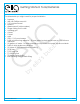
Getting Started: Tools/Materials Tools/Materials you might need for proper installation • • • • • • • • • • • • • • • • • • • • hammer drill with Phillips screw bit 1/2" notched trowel spatula grease pencil (china marker) Auger mixing tool for drill caulking gun 4' level 2' level nails (50+) 1 1/4" wood screws solid wood flooring adhesive - (2) one gallon buckets per shower or 100% silicone adhesive (2) gallons of water - for mixing bedding compound and water test around drain tube of white bathroom caulki
Planning your Installation For best results, please read and follow all directions carefully. 1. Avoid exposure to weather. Product carton is not waterproof. Carton exposed to rain or snow may result in accumulated water penetrating the back laminates of the shower pan and soak the glassed in reinforcement supports causing bulges in the gel coat surface. 2. Most handling damage is the result of impact blows to the back of the fiberglass units. 3. Never drag this fiberglass product on any surface.
Planning your Installation Continued 3. Following the shower pan installation, place the back wall sections, then the side walls. The parts are indexed to one another by a slot and pin connection system. The parts are pushed tight together before connection to the framing pocket is made. To have a successful installation, two persons are required. 4. Plan for the location of the shower water control valve.
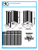
Framing Diagrams FRAMING DIAGRAMS 3838 4836 6030 C 6030 L-R 6033 C 6033 L-R 6036 C 6036 L-R 6048 6060 6232 6238 5050 A 38 7/8” 48 1/4” 60 1/4” 60 1/4” 60 1/4” 60 1/4” 60 1/4” 60 1/4” 60 1/4” 60 1/4” 62 5/8” 62 5/8” 50 1/4” www.ellasbubbles.
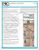
Installation Instructions 1. Prepare the installation area by sweeping the area completely clean. 2. Framing pocket must be sized according to the information provided in the Framing Diagram. It is recommended that the front studs at each side be doubled for added strength. Framing must be extremely square and plumb in order to accomplish a successful installation. 5. 1 of 12 A complete dry fit for the shower base and walls is recommended.
Installation Instructions 2 of 12 Once the hasstep been the fit pan to the studs The fit next is todone dry fitand the shower 8.dry confirmed, and disassemble components. Resume confirm thethe drain location. step 5 and follow each step carefully. The better fit of the pan, the better all wall parts will 6. Carefully measure the framing pocketgaps to assure it assemble as intended with minimal at the seams. is of proper size for the unit to be installed.
Installation Instructions 3 of 12 10. Confirm the pan is level by using a long level on top of the threshold, and along the sides and back. Wipe away any excess caulking that may have squeezed out on the inside of the pan. NOTE: The level is used on the same horizontal surface that has the pins. This will be important to allow the wall panels to fit correctly. See Figures 9A and 9B Now secure the pan in the upright position to the back framing.
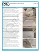
Installation Instructions 4 of 12 14. A solid wood floor adhesive or 100% silicone adhesive will be used to “glue” the bottom side of the shower pan to the sub floor. The following steps will detail the appropriate steps to accomplish this. NOTE: The working life of the flooring adhesive is roughly one hour. (Refer to the label on the adhesive for actual working time). After step 16 is complete, the entire installation process though step 23 must continue.
Installation Instructions 5 of 12 Rotate the pan back to the horizontal position. As you lower the pan to the sub floor, align the drain pipe with the drain fitting, and with the pencil mark at the front of the threshold. Lift the wall panel with the valve hole away. Complete the valve installation and connection to hot and cold water supply at this time. Also complete shower supply connection. Strap pipes to framing if required.
Installation Instructions 6 of 12 21. If all fits are good, proceed with the installation of the back wall. The installation procedures described in this step apply for installation of one or two piece back walls. Wipe clean the ledges on top of the pan. Apply a continuous bead of 100% RTV silicone caulking along the back ledge of the pan where the back wall will sit. The bead should be placed at the middle of the ledge, and be 3/8” wide. The bead should go completely around each alignment pin.
Installation Instructions 7 of 12 Pre-drill holes and attach with screws along the top back flange into the framing studs. Make sure the two wall panels are in alignment and are level and plumb. Place level or straight edge on both vertical flange where the wall will mate to the back wall and check to assure there are no gaps. (For the 4836 four piece which has a single piece back wall panel, skip this step). 23.
Installation Instructions 8 of 12 Lift the side wall and place it on the pan. Make sure alignment pins on the pan and back wall line up. Clear fingers and slide the wall into the installed position. See Figure 25 Install temporary 2 x 4 stud bracing so they sit on top of these wood pieces. Attach these studs to the room framing above the shower, or pad to the ceiling. See Figure 26 Confirm fit and level. Inspect that the grout lines on 26. Remove the temporary bracing after 72 hours.
Installation Instructions 9 of 12 3. Place the seat against the wall of the shower where you want the seat to be located. Seat may be centered on the wall for a Barrier Free installation. 1. Cut off tip of caulk tube diagonally with opening no larger than 1/8". Figure 27 2. Run a continuous bead of caulk at the seam between the two parts. Figure 28 3. Smooth caulk gently with a wet fingertip. Figure 29 m Caulking Instructions 4. Using a clean rag, wipe off excess water and caulk.
Installation Instructions 10 of 12 4. Determine the position you want the to install the bar. Place the bar against the wall. Using a pencil, mark the location of each mounting hole at both ends of the bar. 5. Using a power drill with a 1/4" diameter carbide tipped drill bit, drill, each mounting hole. 6. Apply silicone caulking around and inside each drilled hole before installing the grab bar. 7. Take two (2) of the #10 x 2" Stainless Steel screws.
Installation Instructions 11 of 12 Identifying proper mounting location: It will be helpful to determine whether your Gel-coat or Acrylic reinforced shower unit model has a small molded ridge or “water runoff assist” or trench design on your unit. You will find this feature on the floor of approximately 1-3 inches from the front entry edge of your shower unit. The inside edge of the water retainer should rest on the crown of the ridge allowing the water to run off properly.
Installation Instructions 12 of 12 STEPS LESS FINISHED END CAPS 1. Thoroughly clean threshold surface of all soap scum and debris using standard bath cleanser. Chemically clean surface with rubbing alcohol or equal. 2. Verify the required length anticipating the radius shaping required on each end of the strip. 3. Determine the shape of the end cut required for proper fit and finishing. 4. Begin at one end only. 5. Create template of wall shape (if necessary) with cardboard or material of choice. 6.
Collapsible Dam Tools you might need for proper installation • • • • • • • • Utility knife Tape measure Straight edge Clear or white silicone adhesive caulk Masking tape Rubbing alcohol Bucket of water Clean rags Thank you for purchasing Praxis Bath-ware. For best results, please read and follow all directions carefully.
Collapsible Dam Continued 7. Peel, stretch, alien and pull remaining half to wall. Press into place. SIZE VERIFICATION CHART FOR ALL FACTORY MANUFACTURED SHOWER UNITS 8. Push in the male end of your end cap into the water retainer. Adhere end cap to unit with adhesive caulk and wipe clean. White or clear adhesive type caulk is recommended. SIZE SHOWER & PART NUMBER 9. Use masking tape to temporarily hold cap in place until adhesive cures. 48" barrier free (45-46" I.D opening) 10.
Collapsible Continued 12. Dry fit end caps to insure proper fit. (Trim length if required after stretching & adhering dam) 13. Once proper fit is verified, prepare to apply silicone adhesive caulking. 14. Apply quality silicone adhesive caulking to floor, side wall and male insert end of cap. Push in the male end of your end cap into the water retainer. 15. Wipe clean with rubbing alcohol. 16. Allow 12 hours until adhesive cures before use. 17.
Ella Accessible Shower In A Box Warranty Information For all customers of private labels who complete the Ella’s Bubbles Product Registration Form and return the same to the Ella’s Bubbles Corporate Office, Ella’s Bubbles will use its best efforts to facilitate any customer warranty claim.
Warranty Activation Form Model: Serial Number: Purchase Date: Purchase Price: 1 of 2 Place of Purchase: Contact Name: Phone Number: Upon completing the installation of an Ella Walk In Bath, the following Warranty Activation Form must be completed, signed by both the customer and installer, and returned to Ella’s Bubbles, LLC. In order for the Warranty to be activated (faxed, scanned, or emailed, or hard copy mailed).
Warranty Activation Form 2 of 2 OWNER’S INFORMATION: ______________________________________ Name _______________________________________________ Address City State ZIP ____________________ Telephone ________________________________ E-mail ___________________________ Date _________________________________________ Signature INSTALLER’S INFORMATION: ______________________________________ Company Name Installer’s Name _______________________________________________ Address City State ZIP _____________