Generation II for Conventional Baths Installation Instruction Manual For use by Tub Manufacturers or Qualified Service Personnel ONLY. Ella's Bubbles, LLC | www.ellasbubbles.
Important Safety Instructions PLEASE READ CAREFULLY PRIOR TO Troubleshooting and Servicing Electrical Equipment Definitions WARNING May cause serious injuries or death CAUTION May cause property damage For information on Ella's Bubbles Instructions, see: www.ellasbubbles.com When installing and using this electrical equipment, basic safety precautions should always be followed, including: WARNING Keep dry. Replace control if exposed to water, moisture or contamination.
Generation II for Conventional Baths Installation Instruction Manual Table of Contents Tools & Additional Materials Needed for Installation……...…….....P.4 System Components…...……….………………………...…………. P.5 Design Guide and Installation Procedure.……………….………... P.7 www.ellasbubbles.
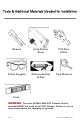
Tools & Additional Materials Needed for Installation Wrench Hack & Hole Saws PVC Pipe Cutter Safety Goggles Silicone Sealant & Gun Tape Measure Level WARNING: The part #30900 ABS-PVC Cement that is included MUST be used on all PVC fittings. Failure to do so may compromise the integrity of system. Page 4 www.ellasbubbles.
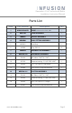
Generation II for Conventional Baths Installation Instruction Manual Parts List Item Part Number 1 MB2G07500XCB 2 Description Qty PUMP without air switch, bulk 1 MBPTA2 TANK ASSEMBLY 1 3 MBNZA NOZZLE ASSEMBLY 1 4 MBWBA1 5 MBWB1 Wall Body 1 6 449038 Plug 3/8 Inch 2 7 MBAIA2 AIR INJECTOR ASSEMBLY 1 8 MBPUA-100 DISCHARGE ASSEMBLY 9 700100 90° elbow 1"MPT X 1" SKT 1 10 437130 Reducer bushing 1" X 1/2" SPG X SKT 1 11 700103 1/2 " PVC Pipe X 1.
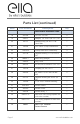
Parts List (continued) Item Part Number Description Qty ADDITIONAL REQUIRED ITEMS 18 401005 1/2" PVC TEE SKT 2 19 438071 Adaptor, 1/2" SPG X 1/8" FPT, PVC 1 20 64774 Adapter fitting 1/8" NPT X 1/8" Hose Barb 1 21 700302 PVC Union 1/2 Slip Schedule 40 2 22 700125A Clamp Hose 9/32" Double Grip 4 23 437130 Reducer bushing 1" X 1/2" SPG X SKT 1 24 MBWF1 Wall Fitting (Flange) 1 25 449010 Plug 1 Inch 1 26 402101 3/4 X 3/4 X1/2 SXSXFIPT PVC TEE 1 27 700104 Coupling 1/2" SK
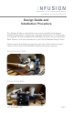
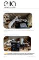
Generation II for Conventional Baths Installation Instruction Manual Design Guide and Installation Procedure This Design Guide is intended for use only by qualified tub design/ assembly personnel. It serves as a generic starting point in helping you to integrate the Ella's Bubbles MicroBubble System into your particular Bath System, with the assistance of your Ella's Bubbles Design Team.
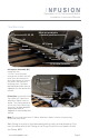
Discharge Side Pump Inner Side Note It is recommended that all parts are dry-fitted until the design is complete. Pump Install the Pump at a level that it is at least 1” higher than both the Suc-tion and Discharge fittings, and run its Suction and Drain Port pipes with a slight downward slope to provide the required self-drainage. For more detailed information refer to Appendix 1 at the end of this manual. Pressure Tank Observe the same recommendations when locating the Pressure Tank.
Generation II for Conventional Baths Installation Instruction Manual Suction Line 31-33, 35 Must be installed in a vertical position. 30 1.5” Piping 35” Piping Slope Downwards 7 27 26 16 17 15 14 13 Suction Assembly Air Injector Assembly (#7) Install with the “FLOW” arrow pointed towards the suction line and away from dis-charge line (long side closest to suction line, short side closest to discharge line). For more detailed information refer to Appendix 3 at the end of this manual.
Discharge 28 8 Discharge 11 Assembly 12 4.5” Piping 2 10 9 18 1.5” Piping 29 1.5” Piping Install fittings as shown. PVC Union 700301 comes pre-installed on the pressure tank. Pressure Tank and Discharge PVC Piping 2 21 PVC Piping 36 CAUTION Disassembly or modification of the Pressure Tank (#2) may damage the system and will void the warranty of the system. No serviceable parts inside. Page 10 www.ellasbubbles.
Generation II for Conventional Baths Installation Instruction Manual Nozzle & Wall Fitting 25 3 6 20 19 18 21 PVC Piping 23 5, 24 The PVC pipe in between the Microbubble Nozzle (#3) and Wall Fitting (#24) should be kept as short as possible. For more detailed information refer to Appendix 5 at the end of this manual. Note Nozzle (#3) must be oriented as shown for proper drainage. Drain Line 22 22 Run a Drain Line from the Pump Drain Port down to the Nozzle Barb.
Infusion™ Microbubble Therapy Walk In Tub Installation Sketch BILL OF MATERIALS PUMP DRAINAGE Pump must be mounted so that the base is at a higher level then the suc on and discharge fi ng. It is necessary that the suc on and discharge lines be at a slight dra for proper draining. PRIME PORT INSTALLATION The prime port must be installed at a level of 2 inches below the water level of the tub. Make sure the barb connec on is poin ng downward.
INFUSION™ Installation Guide MB15000XCB PUMP PLACEMENT (MB15000XCB) - APPENDIX 1 MBPTA When moun ng the pump, the height must be at a level so the drain port is a minimum of one inch above the top of the suc on fi ng for proper drainage PRESSURE TANK ASSEMBLY (MBPTA) - APPENDIX 2 The MBPTA(4) is supplied fully assembled. Two 1/2 inch elbows are supplied unconnect‐ ed to the tank. The tank has been assembled using a torque of 95 . lbs to secure lid to body.
Installation guidelines continued... MBWBA1 WALL BODY (MBWB) One Wall Fi ng(7) and one Body(7A) are provided for the tub installa on and are to be installed equal distance from each other. Note: Trim Fi ng MBTF‐XX (7B) is sold separately because they come in different color finishes. (To be specified by customer at the me of purchase.) MBPUA‐100 MBPUA‐100 1/2 inch PUMP UNION ASSEMBLY‐DISCHARGE (MBPUA‐100) The pump discharge piping is 1/2 inch.