Edition: 1.1.
Table of contents Table of contents 1 Foreword . . . . . . . . . . . . . . . . . . . . . . . . . . . . . . . . . . . . . . . . . . . . . . . . . . . . . . . . . . . . . . . . . . . 4 1.1 1.2 1.3 1.4 1.5 1.6 1.7 1.8 Principles . . . . . . . . . . . . . . . . . . . . . . . . . . . . . . . . . . . . . . . . . . . . . . . . . . . . . . . . . . . . . . . . . . . Target group . . . . . . . . . . . . . . . . . . . . . . . . . . . . . . . . . . . . . . . . . . . . . . . . . . . . . . . . . . . . . . . . .
Table of contents 7 Maintenance and repair . . . . . . . . . . . . . . . . . . . . . . . . . . . . . . . . . . . . . . . . . . . . . . . . . . . . . . . 20 7.1 7.2 7.3 7.4 Ensuring operational safety . . . . . . . . . . . . . . . . . . . . . . . . . . . . . . . . . . . . . . . . . . . . . . . . . . . . . Maintenance work . . . . . . . . . . . . . . . . . . . . . . . . . . . . . . . . . . . . . . . . . . . . . . . . . . . . . . . . . . . . 7.2.1 Changing the oil . . . . . . . . . . . . . . . . . . . .
Foreword 1 Foreword 1.1 Principles These operating instructions: 1.2 • are a part of the following contact free running claw vacuum pumps C-VLR 301. • describe how to use them safely and properly in all life phases. • must be available where the equipment is used. Target group The target group for these instructions is technically trained specialists. 1.3 Supplier documentation and accompanying documents Document Contents No.
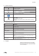
Foreword 1.6 Symbols and meaning Symbol Explanation Condition, pre-requisite #### a), b),... Instructions, action Instructions in several steps Results [-> 14] Cross reference with page number Information, note Safety symbol Warns of potential risk of injury Obey all the safety instructions with this symbol in order to avoid injury and death. 1.
Safety 2 Safety The manufacturer is not responsible for damage if you do not follow all of this documentation. 2.1 Warning instruction markings Warning Danger level Consequences if not obeyed DANGER immediately imminent danger Death, severe bodily injury WARNING possible imminent danger Death, severe bodily injury CAUTION possible hazardous situation Slight bodily injury possible hazardous situation Material damage NOTICE 2.
Safety 2.3 Designated use The machine must only be operated in such areas as are described in the operating instructions: • only operate the machine in a technically perfect condition • do not operate the machine when it is only partially assembled the machine must only be operated at an ambient temperature and suction temperature of between 5 and 40°C. Please contact us for temperatures outside this range.
Safety 2.5 Personal qualifications and training • Ensure that people entrusted with working on the machine have read and understood these operating instructions before starting work, particularly the safety instructions for installation, commissioning, maintenance and inspection work.
Safety 2.8 2.9 Safety instructions for installing, commissioning and maintenance • The operator will ensure that any installation, commissioning and maintenance work is carried out by authorised, qualified specialists who have gained sufficient information by an in-depth study of the operating instructions. • Only work on the machine when it is idle and cannot be switched on again • Ensure that you follow the procedure for decommissioning the machine described in the operating instructions.
Transport, storage and disposal 3 Transport, storage and disposal 3.1 Transportation 3.1.1 Unpack and check the delivery condition a) Unpack the machine on receipt and check for transport damage. b) Notify the manufacturer of transport damage immediately. c) Dispose of the packaging in accordance with the local regulations in force. 3.1.
Transport, storage and disposal 3.2 Storage NOTICE Material damage caused by improper storage. Ensure that the storage area meets the following conditions: a) dust free b) vibration free 3.2.1 Ambient conditions for storage Ambient conditions Value Relative humidity 0% to 80% Storage temperature -20°C to +70°C The machine must be stored in a dry environment with normal air humidity. It should not be stored for more than 6 months. see Info „Machine storage guidelines“, Page 4 3.
Set up and operation 4 Set up and operation 4.1 Setup N A F E F E O P N H D M P1 Q F B F K B1 Fig. 2 Vacuum pump C-VLR 301 A Vacuum connection K Oil discharge point with magnet B Air outlet connection M Oil recommendation plate B1 Exhaust silencer N Data plate D Suction flange O Direction of rotation arrow E Cooling air inlet P Drive motor F Cooling air outlet P1 Motor data plate H Oil filling point Q hot surfaces > 70°C I Oil sight glass 12 | www.
Set up and operation 4.1.1 Data plate 6 1 3 2 4 61 6& YDFXXP SXPS & 9/5 PEDU DEV (1 6 ,' Pñ K N: PLQ 0DGH LQ *HUPDQ\ 5RJJHQEDFKVWUDVVH ' 6FKRSIKHLP ZZZ JG HOPRULHWVFKOH FRP 9 Fig. 3 4.2 8 5 1 Type/ Size (mechanical version) 2 Serial number 3 Year of construction 4 Item no. 5 Final pressure (abs.
Installation 5 Installation 5.1 Preparing for installation Check the following points: • • Machine freely accessible from all sides Do not close ventilation grids and holes • Sufficient room for installing and removing pipes and for maintenance work, particularly for installing and dismantling the machine • No external vibration effects • Do not suck any hot exhaust air from other machines into the cooling system. The oil filling point (Fig. 2/H), oil sight glass (Fig.
Installation 5.3 Connecting pipes a) Vacuum connection at (Fig. 2/A). b) Connect the vacuum line. NOTICE Material damage resulting from the forces and torques of the pipes on the unit being too high. Only screw pipes in by hand. The pumping capacity of the vacuum pump is reduced if the suction pipe is too narrow and/or too long. c) The extracted air can be discharged through the exhaust silencer (Fig. 2/B) or conducted away via a pipe.
Installation 5.4 Filling with lubricating oil a) Fill the lubricating oil (for suitable types see “Maintenance”) for the gear wheels and oil filling point (Fig. 2/H) up to the middle of the sight glasses (Fig. 2/I). b) Close the oil filling point. 5.5 Connecting the motor DANGER Danger of death if the electrical installation has not been done professionally. The electrical installation must only be done by a qualified electrician observing EN 60204. The operating company has to provide the main switch.
Commissioning and decommissioning 6 Commissioning and decommissioning 6.1 Commissioning WARNING Improper use May lead to severe or fatal injuries. Therefore be sure to obey the safety instructions. CAUTION Hot surfaces When the machine is at operating temperature the surface temperatures on the components (Fig. 2/ Q) may go above 70°C. You must avoid touching the hot surfaces (marked with warning plates).
Commissioning and decommissioning 6.1.1 Checking the rotation direction The intended direction of rotation of the drive shaft is shown by the rotary direction arrow (Fig. 2/O). a) Start the motor briefly (max. two seconds) to check the direction of rotation. When looking at the motor fan, it must rotate anti-clockwise. NOTICE Incorrect direction of rotation Operating in the wrong direction of rotation leads to damage to the machine.
Commissioning and decommissioning 6.2 Decommissioning/ storing Stop the machine a) Switch the machine off. b) If available close the cut off device in the suction and pressure pipe. c) Disconnect the machine from the electricity source. d) Depressurise the machine: Open the pipes slowly. The pressure reduces slowly. e) Remove the pipes and hoses. f) Seal the connections for suction and discharge nozzles with adhesive foil. see also Section 3.2.1, Page 11 6.
Maintenance and repair 7 Maintenance and repair DANGER Danger of death from touching live parts. Before maintenance work disconnect the machine by pressing the main switch or unplugging it and ensure that it cannot be turned on again. WARNING Hot surfaces During maintenance work there is the danger of getting burnt on hot components (Fig. 2/Q) of the machine. Wait for the machine to cool down. 7.
Maintenance and repair 7.2.1 Changing the oil H M K Fig. 4 Changing the oil H Oil filling point I Oil sight glass K Oil discharge point M Oil recommendation plate I NOTICE Always change the oil when the machine is at operating temperature and in an atmospherically ventilated area. If it is not completely emptied the amount that can be refilled is reduced. The waste oil must be disposed of in compliance with the local environmental protection regulations.
Maintenance and repair 7.2.2 Air filtering D Fig. 5 s1 f1 Air filtering D Suction flange f1 Mesh filter s1 Screws NOTICE Insufficient maintenance on the air filter The power of the machine lessens and damage may occur to the machine. Intake air filter: The mesh filter (Fig. 5/f1) must be cleaned by rinsing out or purging or replaced more or less often depending on how dirty the discharged medium is. Remove the suction flange (Fig. 5/D) after undoing the screws (Fig. 5/s1).
Maintenance and repair 7.2.3 Coupling s5 v q k n2 m Fig. 7 The coupling sprocket (Fig. 7/k)) is subject to wear and must be checked regularly (at least once a year). Coupling k Coupling sprocket m Motor n2 Fan housing q Coupling half on the motor side s5 Screws v Fan CAUTION Defective coupling sprocket Defective sprockets may lead to the rotor shaft breaking. To check the coupling switch the motor (Fig. 7/m) off and ensure that it cannot be switched on again. Undo the screws (Fig.
Maintenance and repair 7.3 Repair/ Service a) For on site repair work the motor must be disconnected from the mains by a qualified electrician so that it cannot be started up again accidentally. For repairs use the manufacturer, its branch offices or authorised dealers. Please contact the manufacturer for the address of the service centre responsible for you (see Manufacturer‘s address).
Maintenance and repair 7.4 Spare parts Order spare parts in accordance with the: • Spare parts list: E 8805 ➝ C-VLR 301 • Download the PDF file http://www.gd-elmorietschle.com ➝ Downloads ➝ Product Documents ➝ C-Series ➝ Spare Parts • Parts subject to wear and gaskets are indicated separately on the list • Web site: http://www.service-er.de • Select the type, size and design. NOTICE Fig. 9 Spare parts list (example) Only use original spare parts or parts approved by the manufacturer.
Malfunctions: Causes and elimination 8 Malfunctions: Causes and elimination Fault Cause Troubleshooting Important Machine is switched off by the motor protection switch Mains voltage/ Frequency does not correspond with the motor data Check by qualified electrician Section 5.
Technical Data 9 Technical Data C-VLR 301 Sound pressure level (max.) EN ISO 3744 Tolerance± 3 dB(A) 50 Hz 76 60 Hz 79 dB(A) Weight * kg 270 Length * mm 1093 Width mm 478 Height mm 600 Vacuum connection flange G2 Exhaust air outlet flange G2 Correct amount of oil l 1.5 * The length and the weight may differ from the information listed here depending on the motor manufacturer. You will find more technical data on the data sheet D 885.
www.gd-elmorietschle.com er.de@gardnerdenver.com Gardner Denver Schopfheim GmbH Roggenbachstraße 58 79650 Schopfheim · Deutschland Tel. +49 7622 392-0 Fax +49 7622 392-300 Elmo Rietschle is a brand of Gardner Denver‘s Industrial Products Division and part of Blower Operations.
EC - declaration of conformity 2006/42/EC Hereby the manufacturer confirms: Gardner Denver Schopfheim GmbH Postfach 1260 D-79642 Schopfheim that the machine: of the: vacuum pump Series: C-VLR Type: C-VLR 60, C-VLR 100, C-VLR 120, C-VLR 150, C-VLR 250, C-VLR 251, C-VLR 300, C-VLR 400, C-VLR 500, C-VLR 301, C-VLR 1000 is conform to the regulations of the guideline indicated above.
Safety declaration form for vacuum pumps and components 7.7025.003.17 Page 1 of 1 Gardner Denver Schopfheim GmbH Roggenbachstr. 58, 79650 Schopfheim Phone: +49/(0)7622/392-0 Fax: +49/(0)7622/392-300 Repairs and/or maintenance of vacuum pumps and components will only be carried out if a declaration has been filled in correctly and completely. If not, the repair work cannot be started and delays will result. This declaration must only be filled in and signed by authorised qualified staff. 1.