Edition: 1.1.
Table of contents Table of contents 1 Foreword . . . . . . . . . . . . . . . . . . . . . . . . . . . . . . . . . . . . . . . . . . . . . . . . . . . . . . . . . . . . . . . . . . . 4 1.1 1.2 1.3 1.4 1.5 1.6 1.7 1.8 Principles . . . . . . . . . . . . . . . . . . . . . . . . . . . . . . . . . . . . . . . . . . . . . . . . . . . . . . . . . . . . . . . . . . . Target group . . . . . . . . . . . . . . . . . . . . . . . . . . . . . . . . . . . . . . . . . . . . . . . . . . . . . . . . . . . . . . . . .
Table of contents 7 Maintenance and repair . . . . . . . . . . . . . . . . . . . . . . . . . . . . . . . . . . . . . . . . . . . . . . . . . . . . . . . 18 7.1 7.2 7.3 7.4 Ensuring operational safety . . . . . . . . . . . . . . . . . . . . . . . . . . . . . . . . . . . . . . . . . . . . . . . . . . . . . Maintenance work . . . . . . . . . . . . . . . . . . . . . . . . . . . . . . . . . . . . . . . . . . . . . . . . . . . . . . . . . . . . 7.2.1 Check and clean filter bags . . . . . . . . . . . . . . . .
Foreword 1 Foreword 1.1 Principles These operating instructions: 1.2 • are a part of the following radial blower (suction units) models F-CEVF 3718-3 (29), (30), (39) and F-CEVF 3718-4 (29). • describe how to use them safely and properly in all life phases. • must be available where the equipment is used. Target group The target group for these instructions is technically trained specialists. 1.3 Supplier documentation and accompanying documents Document Contents No.
Foreword 1.6 Symbols and meaning Symbol Explanation Condition, pre-requisite #### a), b),... Instructions, action Instructions in several steps Results [-> 14] Cross reference with page number Information, note Safety symbol Warns of potential risk of injury Obey all the safety instructions with this symbol in order to avoid injury and death. 1.
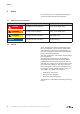
Safety 2 Safety The manufacturer is not responsible for damage if you do not follow all of this documentation. 2.1 Warning instruction markings Warning Danger level Consequences if not obeyed DANGER immediately imminent danger Death, severe bodily injury WARNING possible imminent danger Death, severe bodily injury CAUTION possible hazardous situation Slight bodily injury possible hazardous situation Material damage NOTICE 2.
Safety 2.3 Designated use The machine must only be operated in such areas as are described in the operating instructions: 2.4 • only operate the machine in a technically perfect condition • do not operate the machine when it is only partially assembled • the machine must only be operated at an ambient temperature of between 5 and 40°C, the temperatures of the media handled may not exceed 50°C Please contact us for temperatures outside this range.
Safety 2.5 Personal qualifications and training • Ensure that people entrusted with working on the machine have read and understood these operating instructions before starting work, particularly the safety instructions for installation, commissioning, maintenance and inspection work.
Safety 2.8 2.9 Safety instructions for installing, commissioning and maintenance • The operator will ensure that any installation, commissioning and maintenance work is carried out by authorised, qualified specialists who have gained sufficient information by an in-depth study of the operating instructions. • Only work on the machine when it is idle and cannot be switched on again • Ensure that you follow the procedure for decommissioning the machine described in the operating instructions.
Transport, storage and disposal 3 Transport, storage and disposal 3.1 Transportation 3.1.1 Unpack and check the delivery condition a) Unpack the machine on receipt and check for transport damage. b) Notify the manufacturer of transport damage immediately c) Dispose of the packaging in accordance with the local regulations in force. 3.1.2 Lifting and transporting WARNING Hurt or limbs crushed as a result of the items being transported falling or tipping over.
Transport, storage and disposal 3.2 Storage NOTICE Material damage caused by improper storage. Ensure that the storage area meets the following conditions: a) dust free b) vibration free 3.2.1 Ambient conditions for storage Ambient conditions Value Relative humidity 0% to 80% Lagertemperatur -10°C to +60°C The machine must be stored in a dry environment with normal air humidity. It should not be stored for more than 6 months. 3.
Set up and operation 4 Set up and operation 4.1 Setup e1 A B B G1 N Fig. 2 Radial blower (Suction unit) F-CEVF (29) A Suction connection e1 Filter cover B Exhaust air exit h1 Filter housing N Data plate x1 Clips G1 Motor starter y1 Clips 12 | www.gd-elmorietschle.
Set up and operation 4.1.1 Data plate 2 1 3 5 4 Bauj./Nr. 10 6 3~ Mot. 2861499 Typ CEVF 3718-3 (29) 1016053110 pmax. - 47 mbar max. 360 m³/h Y Δ/ 220/380 V ± 10% 5,40/3,10 A 50 Hz EN 60034 S1 2850 min-1 1,1 kW 13 12 11 Fig. 3 Data plate 4.2 10 9 8 7 1 Type/ Size (mechanical version) 2 Year of construction 3 Serial number 4 Motor design 5 Item no.
Installation 5 Installation 5.1 Preparing for installation Check the following points: • • Machine freely accessible from all sides Do not close ventilation grids and holes • Sufficient room for installing and removing pipes and for maintenance work, particularly for installing and dismantling the machine • No external vibration effects • Do not suck any hot exhaust air from other machines into the cooling system. When installing the blower make sure there is a space of 0.
Installation 5.3 Connecting suction pipe a) Connect the suction pipe at suction connection (Fig. 2/A). NOTICE Long and/or small bore pipework should be avoided as this tends to reduce the capacity of the blower. The units should be used only shortly with a fully closed inlet or when not connected to a system. 5.4 Connecting the motor DANGER Danger of death if the electrical installation has not been done professionally.
Commissioning and decommissioning 6 Commissioning and decommissioning 6.1 Commissioning WARNING Improper use May lead to severe or fatal injuries. Therefore be sure to obey the safety instructions. CAUTION Noise emission The highest noise pressure levels measured as per EN ISO 3744 are given in Section 9. When spending a long time in the vicinity of the running machine use ear protectors to avoid permanent damage to your hearing. NOTICE During operation the filter cover (Fig.
Commissioning and decommissioning 6.1.1 Checking the rotation direction The intended direction of rotation of the drive shaft is shown by the rotary direction arrow (Fig. 4/O). a) Start the motor briefly (max. two seconds) to check the direction of rotation. To see the direction of rotation using the aperture (Fig. 4/D). For this the filter housing (Fig. 2/h1) must be removed. Remove clips (Fig. 2/y1), remove filter cover (Fig. 2/e1) complete with filter housing (Fig. 2/h1).
Maintenance and repair 7 Maintenance and repair DANGER Danger of death from touching live parts. Before maintenance work disconnect the machine by pressing the main switch or unplugging it and ensure that it cannot be turned on again. 7.1 Ensuring operational safety Regular maintenance work must be carried out in order to ensure operational safety. Maintenance intervals also depend on the operational demands on the machine. With any work observe the safety instructions described in Section 2.
Maintenance and repair 7.2.1 Check and clean filter bags e1 h1 x1 O m D y1 k Fig. 4 Check and clean filter bags O Direction of rotation D Aperture k Filter bags m Motor housing e1 Filter cover h1 Filter housing x1 Clips y1 Clips Therefore open clips (Fig. 4/x1) and remove filter cover (Fig. 4/e1). Remove filter bags (Fig. 4/k), clean and knock out. After 2 or 3 times cleaning the bags also check the inside of the filter housing (Fig. 4/h1). Therefore open clips (Fig.
Maintenance and repair 7.3 Repair/ Service a) For on site repair work the motor must be disconnected from the mains by a qualified electrician so that it cannot be started up again accidentally. For repairs use the manufacturer, its branch offices or authorised dealers. Please contact the manufacturer for the address of the service centre responsible for you (see Manufacturer‘s address).
Maintenance and repair 7.4 Spare parts Order spare parts in accordance with the: • Spare parts list: E 705 ➝ F-CEVF 3718-3 (29), (30), (39) • Download the PDF file http://www.gd-elmorietschle.com ➝ Downloads ➝ Product Documents ➝ F-Series ➝ Spare Parts • Parts subject to wear and gaskets are indicated separately on the list. • Web site: http://www.service-er.de • Select the type, size and design. NOTICE Fig.
Malfunctions: Causes and elimination 8 Malfunctions: Causes and elimination Fault Cause Troubleshooting Important Machine is switched off by the motor protection switch Mains voltage/ Frequency does not correspond with the motor data Check by qualified electrician Section 5.5 Blower operates without connection to a system Connect system Section 5.3 Filter bags are contaminated or full Clean or discharge filter bags Section 7.2.
Technical Data 9 Technical Data F-CEVF 3718 (29), (30), (39) Sound pressure level (max.) EN ISO 3744 Tolerance± 3 dB(A)) Weight 1,1 kW 1,5 kW 50 Hz 75 76 60 Hz 76 77 3718/3 40 - 3718/4 - 44 dB(A) kg Diameter mm 474 Width mm 549 Height mm 3718/3 494 3718/4 542 You will find more technical data on the data sheet D 705 • Download the pdf file: D 705 ➝ F-CEVF 3718-3 + 3718-4 (29) • Download the pdf file: http://www.gd-elmorietschle.
www.gd-elmorietschle.com er.de@gardnerdenver.com Gardner Denver Schopfheim GmbH Roggenbachstraße 58 79650 Schopfheim · Deutschland Tel. +49 7622 392-0 Fax +49 7622 392-300 Elmo Rietschle is a brand of Gardner Denver‘s Industrial Products Division and part of Blower Operations.
EC - declaration of conformity 2006/42/EC Hereby the manufacturer confirms: Gardner Denver Schopfheim GmbH Postfach 1260 D-79642 Schopfheim that the machine: of the: Radial blower Series: F-CEVF Type: F-CEVF 3718-3, F-CEVF 3718-4 is conform to the regulations of the guideline indicated above.
Safety declaration form for vacuum pumps and components 7.7025.003.17 Page 1 of 1 Gardner Denver Schopfheim GmbH Roggenbachstr. 58, 79650 Schopfheim Phone: +49/(0)7622/392-0 Fax: +49/(0)7622/392-300 Repairs and/or maintenance of vacuum pumps and components will only be carried out if a declaration has been filled in correctly and completely. If not, the repair work cannot be started and delays will result. This declaration must only be filled in and signed by authorised qualified staff. 1.